13 minute read
TMS800E OPERATOR’S MANUALOPERATING CONTROLS AND PROCEDURES


Engine Idle Switch
This switch (35) is a two position (+/-) momentary rocker switch on the left side of the front console in the carrier cab. It provides idle-control inputs that increase and decrease the engine idle.
Engine Wait To Start Indicator
The engine wait to start indicator (30) is located on the top left side of the front console. It illuminates amber for a period of time when the ignition switch is turned to the on position. The engine should not be cranked until the wait to start indicator turns off and a solid “N” is visible in the transmission gear display (see item 57).
Travel Controls and Indicators
Dual Air Pressure Gauge
The dual air pressure gauge (1) is located on the right side of the front console. The gauge is a direct reading pressure gauge with two indicating pointers, red for the primary system and green for the secondary system. The gauge has a dual scale calibrated from 100 to 1000 kPa and 0 to 150psi. The gauge is connected to each air system separately through tubing.
Low Air Pressure/Tire Inflation On Indicator
The low air pressure/tire inflation on indicator (27) is located on the top left side of the front console. The indicator illuminates red when the pressure in either or both air systems is below 517 kPa (75 psi). The indicator is controlled by two pressure switches electrically connected in parallel. To determine which system pressure is low, observe the dual air pressure gauge. In addition to illuminating the indicator, a warning buzzer will sound.
The bottom of the indicator illuminates amber when the pressure switch in the tire inflation system is activated. In addition to illuminating the indicator, a warning buzzer will sound.
Speedometer
The speedometer (4) is located in the center of the front console above the steering wheel. The speedometer indicates road speed in both km/hg (kilometers per hour) and mph (miles per hour).
Odometer
There is an odometer (16) located at the bottom of the speedometer and shows total distance traveled.
Parking Brake Control
NOTE: The park brake must be set before the outrigger controls will operate.
The parking brake control (12) is located on the right side of the front console. The control is a push-pull type air valve used to apply and release the parking brakes on all four rear wheels.
Park Brake Engaged Indicator
The park brake engaged indicator (29) is located at the top of the front console. The indicator illuminates red when the crane parking brakes are appl ied. It is illuminated by a pressure switch on the parking brake valve.
The bottom of the indicator illuminates red to warn the operator that the swing brake release pressure is not enough to hold the swing brake disengaged during trailing boom operation. In addition to illuminating the indicator, a warning buzzer will sound.
Cross-Axle Differential Locked Indicator (Optional)
The cross-axle differential locked indicator (26) is located at the left center side of the front console. The amber indicator illuminates to show that the cross axle differential is locked.
Caution
Do not operate the cross axle differential lock or the interaxle differential lock on dry roads.
Published 12-22-2008, Control # 107-09
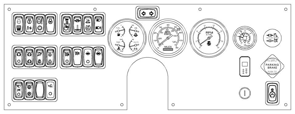
ItemDescription
1Dual Air Pressure Gauge
2Tachometer
3Left Turn Signal Indicator
4Speedometer
5Gauge Cluster (fuel, temperature, oil, volts)
6Right Turn Signal Indicator
7Heater On/Off Switch
8Heater/Air Conditioner Fan Switch
912 Volt Accessory Outlet
10Air Conditioner Switch (Optional)
11 Trailing Boom Trailer Emergency Brake Control (Optional)
12Parking Brake Control
13Windshield Wiper/Washer Switch
14Ignition Switch
15Inter-Axle Differential Lock Switch
16Odometer
17Cross-Axle Differential Lock Switch (Optional)
18Tire Inflation Switch
19Beacon Light Switch (Optional)
ItemDescription
20Engine Brake High-Low Switch
21Headlights Switch
22Engine Brake On/Off Switch
23Engine Stop/Module Off Line Indicator
24Engine Warning/Electrical Diagnostic Indicator
25 Engine Coolant Temperature/Auxiliary Transmission Low Indicator
26
Cross-Axle Differential Locked Indicator (Optional)
27Low Air Pressure/Tire Inflation On Indicator
28High Beam/Lamp Malfunction Indicator
29 Park Brake Engaged/Swing Brake Engaged Indicator (swing brake may be optional)
30Engine Wait To Start Indicator
31Dimmer Switch
32Inter-Axle Differential Lock Indicator
33Suspension Deflated Indicator
34Suspension Inflation Control Switch
35Engine Idle Switch
36Engine Regeneration Switch
37Brake Pedal
ItemDescription
38Throttle Pedal
39Carrier Electrical Diagnostic Connector
40Transmission Shift Lever
41Ash Tray
42Beacon Light (Optional)
43Fire Extinguisher
44Cab Dome Light (Not Shown)
45Steering Wheel
46Horn Button
47 Headlight Dimmer/Turn Signal Lever/Cruise Control
48Seat
49Sun Visor
50Cab Circulating Fan
51Windshield Defroster Air Outlet
52Heater Control Switch
53Cab Marker Lights
54Fuse and Relay Panel (Not Shown)
55Hazard Light Switch
56Steering Column Tilt/Telescope Lever
57Gear Display
58 Regeneration/Exhaust Filter Temperature Indicator
59Auxiliary Transmission Low Range Switch
60Jib Stowage Controller
Cross-Axle Differential Lock Switch (Optional)
The cross-axle differential lock switch (17) is located on the left center side of the front console and is used to lock the right and left wheels in a tandem set. The cross-axle differential lock increases traction on slippery roads. It is a two position lock/unlock switch. Press top of switch for the lock position or bottom of switch for the unlock position.
Caution
Do not operate cross-axle differential lock while crane wheels are spinning or at speeds over approximately 16 km/h (10 mph). Release the throttle when locking or unlocking.
Inter-Axle Differential Lock Switch
The inter-axle differential lock switch (15) is located on the left center side of the front console. In the lock (press top of switch) position, both rear axles are locked together and turning at the same speed. In the unlocked (press bottom of switch) position, the axles operate independently of each other.
Caution
Do not operate inter-axle differential lock switch while crane wheels are spinning or at speeds over approximately 16 km/h (10 mph). Release the throttle when locking or unlocking.
Inter-Axle DIfferential Lock Indicator
The inter-axle differential lock indicator (32) is located on the left center side of the front console. The amber indicator illuminates when the inter-axle differential lock is engaged.
Brake Pedal
The brake pedal (37) is located on the cab floor, to the left of the foot throttle and is used to apply the service brakes.
Transmission Shift Lever
The transmission shift lever (40) is located on the right side of the cab. It is used to select the transmission gears. Refer to OPERATING PROCEDURES in this section for complete transmission operating instructions.
Gear Display
The gear display (57) is located on the right side of the front console. It displays the current transmission gear. This display is also used to retrieve transmission fault codes.
Trailing Boom Trailer Emergency Brake Control (Optional)
The TRAILING BOOM (TRA ILER EMERGENCY) brake control (11) is a push-pull type air valve located on the right side of the front console. The control is used to set and release the brakes on the trailing boom trailer.
Swing Brake Engaged Indicator (Optional) swing brake engaged indicator (29) is located on the top left side of the front console. The indicator illuminates when there is sufficient pressure to hold the swing brake disengaged during trailing boom operation. In addition to illuminating the indicator, a warning buzzer will sound.
Suspension Inflation Control Switch
The suspension inflation control switch (34) is located on the right side console. When positioned to the right to inflate, the suspension air bags are inflated. When positioned to the left to deflate, the suspension air bags are deflated.
NOTE: The suspension air bags should be inflated at all times except when on outriggers or in a pick and carry mode.
Published
Suspension Deflated Indicator
The SUSPENSION DEFLATED indicator (33) is located on the right side console. The amber indicator illuminates when the air is removed from the suspension air bags. It is controlled by four pressure switches connected in series.
Auxiliary Transmission Low Range Switch
The auxiliary transmission low range switch (59) is located on the right side console. Push the switch to the right to engage low range.
Craning Controls and Indicators
Park Brake Engaged/Swing Brake Engaged Indicator
The park brake engaged indicator (29) is located at the top of the front console. The top of the indicator illuminates red when the crane parking brakes are applied. Illumination is determined by a pressure switch on the parking brake valve. The park brake must be set before the outrigger controls will operate.
The swing brake engaged indicator (bottom of the indicator) illuminates red to warn the operator that the swing brake release pressure is not enough to hold the swing brake disengaged during trailing boom operation. In addition, illuminating the indicator, a warning buzzer will sound. (Optional)
Accessory Controls and Indicators
High Beam/Lamp Malfunction Indicator
The headlight high beam/lamp malfunction indicator (28) is located at the top left of the center front console. The indicator is a blue light that illuminates when the headlights are on high beam or amber when there is a lamp malfunction.
Heater On/Off Switch
The heater on/off switch (7) is located on the right side console. Press the right side of the switch to ON for heat. Press the left side of the switch to turn the heater off.
Heater Control Switch
The heater control switch (52) is located on the right side console. Push the switch to the right to (OPEN) the valve for heat. Push the switch to the left to (CLOSE) the valve.
Heater /Air Conditioner Fan Switch
The heater/air conditioner fan switch (8) is located on the right side console. The switch controls the speed which in turn regulates the volume of heated air output of the heater and air conditioner fan by positioning switch to: low (switch positioned to left), medium (switch centered), and high (switch positioned to right).
NOTE: Either air condition or heater switch must be positioned to “on” before the fan will become operational.
Air Conditioner Switch (Optional)
The air conditioning switch (10) is located on the right side console. The switch controls the operation of the optional air conditioning system in conjunction with the fan switch. Press the switch to the right to turn air conditioner on. Press the switch to the left to turn the air conditioner off.
Windshield Wiper/Washer Switch
The windshield wiper/washer toggle switch (13) is located on the lower right side of the front console. The switch is used for removing moisture from the windshield.The switch has an off and high position with six intermittent positions between high and off. Pushing the switch up from the off position energizes the wiper motor. Continue to push switch up for each intermittent position and the high position. Push the switch down to off to stop the motor and return the wiper blade to the parked position.
Push the very top of the switch to activate the washer switch to spray washer fluid on the windshield.
Headlights Switch
The headlights switch (21) is a three position switch located on the bottom left side of the front console. The bottom position is off. The center position will illuminate marker, clearance and gauge lights. The top position will turn on the headlights in addition to the marker, clearance and gauge lights.
Beacon Light Switch (Optional)
The beacon light switch (19) is a two position, on-off switch located on the left side of the front console that controls the beacon light (42) on the top of the carrier cab.
Dimmer Switch
The dimmer switch (31) is located on the left bottom side of the front console. The switch controls the brightness of the gauge lights.
NOTE: The headlight switch (21) must be in the center or top position before gauge lights will illuminate and the dimmer switch becomes functional.
Headlights Dimmer Switch
The headlights dimmer switch (47) is incorporated in the turn signal switch. It is located on the left side of the steering column. The switch is activated by pulling or pushing the turn signal lever toward you or away from you.
Turn Signal Lever
The turn signal lever (47) is located on the steering column. Positioning the lever down causes the indicator light on the console and the left front and left rear signals to flash. Positioning the lever up causes the indicator light on the console and the right front and right rear signals to flash.
Cruise Control
The cruise control (47) is incorporated in the turn signal lever located on the left side of the steering column. Push the switch to ON to turn the cruise control on. Accelerate to desired speed and push (SET COAST) button on end of lever.
If cruise is stopped by braking and switch is still positioned to ON, the switch can be pushed to (RESUME-ACCEL) to resume cruise speed. Position switch to OFF to turn the cruise control off.
Hazard Light Switch
The hazard light switch (55) is located on the steering column. Pulling on the switch (in the direction of the arrow) causes all the turn signals and the indicator light on the console to flash.
Left Turn Signal Indicator
The left turn signal indicator (3) is located on the top left side of the front console. It is a green indicator light that flashes when the turn signal lever or hazard switch is pulled down.
Right Turn Signal Indicator
The right turn signal indicator (6) is located on the top right side of the front console. It is a green indicator light that flashes when the turn signal lever or hazard switch is pushed up.
Steering Column Tilt/Telescope Lever
The steering column tilt/telescope lever (56) is located on the steering column behind the turn signal lever. Pulling back on the lever allows the steering column to be tilted, and pushing forward on the lever allows the steering column to be telescoped in and out.
Horn Button
The horn button (46) is located in the center of the steering wheel (45). Depressing the horn button energizes the circuit sounding the horn.
Fire Extinguisher
The fire extinguisher (43) is mounted on the left inside rear of the cab.
Cab Circulating Fan
The cab circulating fan (50) is mounted on the left front of the cab and is controlled by a two speed rocker switch on the base of the fan.
Tire Inflation Switch
The tire inflation switch (18) is located on the left side of the front console. It is a two position switch that activates the tire inflation system. Push the top of the switch to activate the tire inflation system. An amber indicator will illuminate and the warning buzzer will sound when the switch is in the on position.
12 VDC Accessory Outlet
The 12 vdc accessory outlet (9) is located on the right side console. It provides an outlet for the operator to plug in a 12 vdc accessory. This outlet should be used only for components requiring 8 amps or less.
Cab Dome Light (Not Shown)
The cab dome light (44) is located in the center of the cab roof directly over the seat. It is controlled by a switch on the light and by a door switch that powers the light when the cab door is opened.
Air Horn (Not Shown)
A set of air horns are mounted on top of the cab and are controlled by a valve manually actuated by a cable inside the cab.
Fuse and Relay Panel (Not Shown)
The fuse and relay panel (54) is located on the right rear side of the cab under a removable cover. It contains 8 fuses and various relays that protect and control the various electrical components of the carrier. In addition, it contains the crane’s Master Control Module.
Carrier Electrical Diagnostic Connector
The carrier electrical diagnostic connector (39) is located on the left side of the cab beneath the front console. It is used for servicing the engine ECM, transmission ECM or the crane’s electrical system.
NOTE: A laptop computer with appropriate cable and engine or electrical system software are required.
Published 12-22-2008, Control # 107-09
Additional Carrier Controls and Indicators
NOTE: The following paragraphs describe the additional controls and indicators located on the carrier to operate the outriggers. The numbers in parentheses () represent the index number from (Figure 3-2).
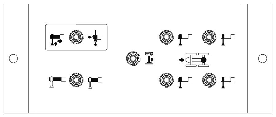
Outrigger Control Summary
There is an OUTRIGGER CONTROL panel located on each side of the crane carrier. Each panel contains switches for extending and retracting the outrigger beams and for raising and lowering the outrigger stabilizer (jack) cylinders on all sides of the crane. Each control panel also contains a control switch for raising and lowering the center front stabilizer. The following paragraphs explain these controls.
Outrigger Control Panel
There is one OUTRIGGER CONTROL PANEL (1) on each side of the unit’s frame. The panel on the right side operates the outrigger beams for that side only. The panel on the left side operates the outrigger beams for that side only. The stabilizers may be operated from the left or right side of the unit.
Outrigger Beam Selector Switch
The OUTRIGGER BEAM SELECTOR switch (2) is used to indicate desired operation of the front or rear outrigger beam for the side of the unit the control panel is on.
Extend/Retract Switch
The EXTEND/RETRACT switch (3) will operate both the outrigger beams or the stabilizers. After positioning the desired selector switch, positioning the extend/retract switch energizes the control solenoid to allow hydraulic fluid to flow through the control solenoid valve and the individual solenoid valve and move the selected component in the desired direction. In addition , when the switch is positioned to either position, a signal is sent to the engine ECM to increase engine speed above idle for operation of the outriggers.
Center Front Stabilizer Switch
The CENTER FRONT STABILIZER switch (4) is located in the center of the outrigger control panel. It must be used in conjunction with the extend/retract switch to control the operation of the center front stabilizer. The center front stabilizer will retract automatically when any of the other four stabilizers are retracted; therefore, it must be reset if lifting is to be continued.
Stabilizer Selector Switch
The STABILIZER SELECTOR switch (5) is used to indicate which stabilizer is desired to operate.
Daytime Running Lights
Daytime running lights is a feature in which the headlight low beams will come on automatically anytime the carrier ignition switch is in the on position, engine is running, and the park brake is released regardless of the position of the headlight switch.
Superstructure Cab
NOTE: The following paragraphs describe all the available (standard and optional) controls and indicators located in the cab. Some machines may not be equipped with the optional controls shown. The numbers in () represent the index number from (Figure 3-3).
NOTE: All rocker switches contain one or two LED’s in the switch for illumination.
Engine Controls and Indicators
Engine Increment/Decrement Switch
The engine increment/decrement switch (31) located on the right side console is used to set the engine operating speed. It is a two position (+/-) momentary switch.
Pushing the top of the switch quickly increases (+) engine RPM to the maximum allowed operating speed. Pushing the bottom of the switch quickly decreases (-) engine RPM to idle speed. Pushing and holding either side of the switch will increase or decrease engine speed. Releasing the switch will hold the engine at the current speed. Pressing the foot pedal will increase engine speed above the “hold” speed. Releasing the foot pedal causes the engine to return to the “hold” speed.
Gauge Cluster
The gauge cluster (29) is located on the left side of the pedestal mounted console beside the LMI panel and contains a voltmeter, oil pressure gauge, water temperature gauge, and a fuel quantity gauge.
Voltmeter
The voltmeter (VOLTS) is located on the lower right of the gauge cluster. With the ignition switch in the run (between vertical and right) position and before starting the engine, the voltmeter indicates the condition of the batteries. With the engine running, the voltmeter indicates output voltage of the alternator. The voltmeter scale is from 10 to 16 volts.
Engine Oil Pressure Gauge
The engine oil pressure (OIL) gauge is located on the upper right of the gauge cluster. The gauge indicates the engine oil pressure on a scale calibrated from zero (0) to 80 psi. It receives a signal from the crane’s electronic operating