OPERATING CONTROLS AND PROCEDURES The left column is the load radius, which is the distance from the axis of the crane rotation to the load center of gravity. The top row lists various boom lengths from fully retracted to fully extended (with swingaway extension). The number at the intersection of the left column and top row is the total load limit for that load radius and boom length. The number in parentheses below the total load limit is the required boom angle (in degrees) for that load. Boom lengths between increments should always be treated as if it were the next longer length. For example, if the actual boom length is 15.2 m (50 ft) and the chart shows boom lengths of 14.6 - 16.4 m (48 - 54 ft), use the load capacity shown in the 16.4 m (54 ft) column.
TMS800E OPERATOR’S MANUAL length and angle, he can quickly determine the tip height and operating radius. A lifting diagram is included for over-side, over-rear, and over-front lifting areas. The lifting area diagram shows that the locations of the outrigger stabilizer cylinders in the full extended position are used to mark the boundaries of the lifting areas. Another section contains notes for lifting capacities. Be sure to read and understand all notes concerning lifting capacities. The load chart also gives weight reductions for Manitowoc/ Grove load handling devices such as hookblocks, overhaul balls, boom extension sections, etc, which must be considered as part of the load. The weight of any other load handling devices such as chains, slings, or spreader bars must also be added to the weight of the load.
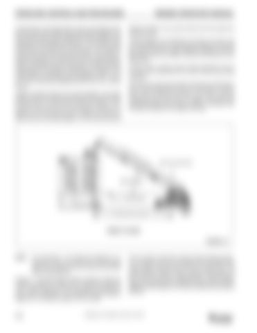
Another important section is the range diagram. The range diagram shows the operating radius and tip height that can be achieved at a given boom length and angle. If the operator knows the radius and tip height required for a specific lift, the angle and boom length can quickly be determined from the range diagram. Or if he knows the boom
MA IN
BO
OM
LE NG
TH
AXIS OF ROTATION
BOOM ANGLE
HORIZONTAL
OPERATING RADIUS
4605
TERMS TO KNOW FIGURE 3-4
NOTE:
The information in the following paragraph is an example of how to compute a lift. The numbers used in the example may not coincide with the load chart in the crane cab.
Problem: A concrete beam weighing 2268 kg (5000 lbs) needs to be lifted to a height of 9.1 m (30 ft) at a radius of 15.2 m (50 ft) (maximum). The range diagram indicates the boom must be extended to 18.9 m (62 ft) in order to reach a height of 9.1 m (30 ft) at a radius of 15.2 m (50 ft).
3-24
First we need to check the crane for load handling devices. In our example, the crane is equipped with a auxiliary boom nose (rooster sheave) and a five ton overhaul ball. The rooster sheave is 50 kg (110 lbs), and the overhaul ball is 78 kg (172 lbs) for a total of 128 kg (282 lbs). The lift requires slings and spreader bars weighing 159 kg (350 lbs) which makes the total weight for the load handling devices 286 kg (632 lbs).
Published 12-22-2008, Control # 107-09


