9 minute read
A Correct use and application


The “Guidelines for the Correct Use and Application of Paver” complied by Dynapac are included in the scope of delivery for the present machine. The guidelines are part of the present operating instructions and must always be followed. Federal, state and local regulations are fully applicable.
The road construction machine described in these operating instructions is a paver that is suited for laying mixed materials, roll-down concrete or lean-mixed concrete, track-laying ballast and unbound mineral aggregates for paving foundations
This machine shall be used, operated and maintained for the purpose of the intended work as included in the operation manual. Any other use is regarded as improper use and can cause injury to persons or damage to the paver or other equipment or property.
Any use going beyond the range of applications described above is regarded as improper use and is expressly forbidden! Especially in those cases where the paver is to be operated on inclines or where it is to be used for special purposes (i.e. construction of dumps, dams), it is absolutely necessary to contact the manufacturer.
Duties of the user: A “user” within the meaning of the present operating instructions is defined as any natural or legal person who either uses the paver himself, or on whose behalf it is used. In special cases (i.e. leasing or renting), the user is considered the person who, in accordance with existing contractual agreements between the owner and the user of the paver, is charged with the observation of the operating duties. The user must ensure that the paver is only used in the stipulated manner and that all danger to life and limb of the operator, or third parties, is avoided. In addition to this, it must be ensured that the relevant presentation regulations and other safety-related provisions as well as the operating, servicing and maintenance guidelines are observed. The user must also ensure that all persons operating the equipment have read and understood the present operating instructions.
Mounting attachments: The paver must only be operated in conjunction with screeds that have been approved by the manufacturer. Mounting or installation of any attachments that will interfere with supplement the functions of the paver is permitted only after written approval by the manufacturer has been obtained. If necessary, the approval of local authorities has to be obtained. Any approval obtained from local authorities does not , however, make the approval by the manufacturer unnecessary.
B Vehicle description
1. Application
The Dynapac F1000T is a rubber track paver that is used for laying bituminous mixed material, roll-down or lean-mixed concrete, track-laying ballast and unbound mineral aggregates for paving foundations.
2. Description of assemblies and functions
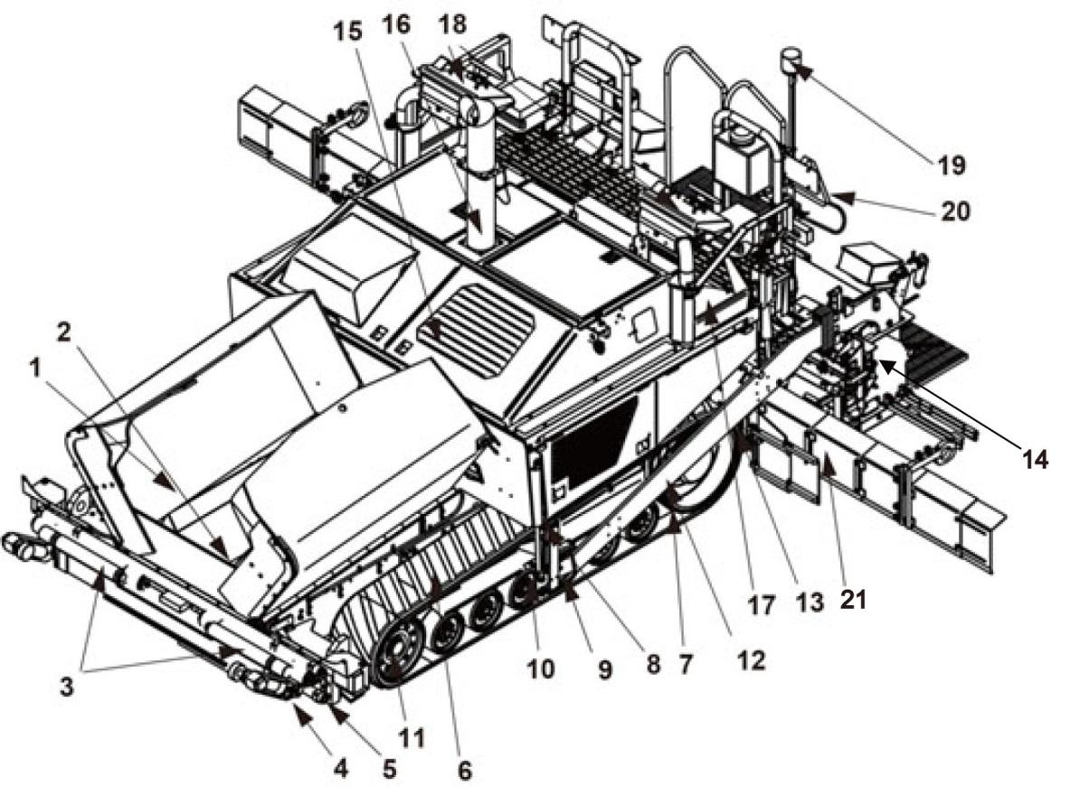
2.1 Vehicle
Construction (Please read and conform the red chapters)
The Dynapac F1000T is a rubber track propelled paver built with a welded steel frame on which the power pack, augers, conveyors, hopper and operator positions are mounted.
The track suspension compensates for uneven areas on the ground. The suspension of the attached screed helps to attain high paving precision. The machine is designed to move material via hydraulically driven conveyor chains and spread it with augers to allow the screed to spread the materials evenly. The adjustable hydrostatic drive system allows the speed of the paver to keep pace with other equipment in all work conditions.
The operation of the paver is largely facilitated by the easy to use operator controls. The operator can control the functions of the paver from either the left control panel or the right control panel.
Available options include:
Grade Control
- Control System
- Averaging Ski
- Non-Contacting Averaging Ski
Truck Hitch
Auger Extensions
Frame Extensions
Umbrella Screed
- Berm
- Screed Corded Controls
- Screed Extensions
Further equipment and upgrade options on request
Engine: The paver is powered by a 6-cylinder, water cooled diesel engine with direct injection and a turbo charger. Electric starting and belt driven alternator battery charging is standard. The engine power / rpm is controlled by the engine speed control on either of the consoles. The engine is shut down either by removing the key “ON/OFF” switch or the emergency stop switch. For further details, see the technical data in the engine’s instruction manual.
Track: The two rubber tracks are driven indepently of each other. They are each direct drive requiring less maintenance and service than chain driven machines. Each track is adjusted automatically using hydraulic pressure. The rubber track allows the machine to attain a high transportation speed with excellent maneuverability and traction.
Hydraulic system: The diesel engine has the Pump Drive gear box attached to it. This drives the hydraulic pumps for all the main and auxiliary paver functions. The hydraulic system also drives the generator needed to heat materials to prevent the material from sticking to the screed plate. All power on the paver comes from hydraulics.
Track drive: The closed-loop track drive system includes two speed track drive motors that are connected to the drive pumps by means of high pressure hydraulic hoses. The hydraulic motors are mounted to the track drive wheels and mobilize the tracks. Track movement is controlled by directional control joysticks on the consoles.
Steering system/operator’s platform: The independent hydrostatic travel drives allow the paver to be turned on the spot. The electronic synchronization, controlled from the operating panel, ensures that the paver runs straight ahead. The operating panels can be secured in variable positions on both left and right console panels, by a locking mechanism.
Steering is accomplished merely by driving one track at a different speed than one other. If turning left, the track on the right hand side will move faster than the track on the left. If turning right, the track on the left hand side will move faster than the track on the right.
Push roller crossbar: The push rollers for material trucks are connected to a crossbar that pivots at its center. This crossbar allows for differences in distances to the rear wheels on a variety of material trucks. This permits the paver to deviate less from its course and makes paving curves easier
Material compartment (hopper): The hopper inlet is equipped with a conveyor system that empties the hopper and transfers the material to the auger. The hopper can hold approximately 30,000 lbs. (13608 kg) and are raised hydraulically to empty onto the conveyor chains. To facilitate the emptying and to improve material transfer, each of the lateral covers of the hopper are hydraulically moved.
Conveyors (Material transfer): The paver is equipped with two conveyors driven separately with pressure from a single pump. The system consists of a single, pressure compensated, load sense style, variable displacement, open loop pump driving two fixed volume hydraulic motors. This pump supplies hydraulic power for both conveyors of the machine and provides power for the cylinders on the machine.
These conveyors transfer the material from the hopper to the augers. By using sensors to monitor the filling height during the paving procedure, the transfer amount or speed regulation is completely automatic.
Augers: The augers are driven and controlled independently from the conveyors. The auger hydraulics consist of two high pressure, variable displacement, closed loop pumps driving two fixed volume motors. The left-hand and the right-hand half of the auger can be controlled separately
The auger direction can be changed to direct material towards the center of the screed or towards the outside of the speed. There is always a sufficient supply of material even if an excessive amount of material is required at one side. The auger speed is controlled by sensors that monitor the material flow leaving the auger area.
Height adjustment and extension of augers: Height adjustment and extension of augers ensure an optimum variety of a wide range of paving thicknesses and widths.
Auger height is regulated at the operating panel and moved by means of hydraulic cylinders.
Auger segments of different lengths can be attached to easily adapt to the different paving widths.
Leveling/slope control system: The slope control system allows the paving thickness to be regulated at the regulated at the left-hand or the right-hand side with a defined difference to the opposite side. To determine the actual value, the two screed leveling arms are linked with a slope beam.
The slope control system always operates in conjunction with the screed height adjustment of the opposite side.
By adjusting the height of the screed leveling cylinders, the paving thickness of the material or the laying height of the screed can be controlled.
Activation occurs electro-hydraulically on both sides and can be controlled manually by means of toggle switches or automatically by means of an electronic grade control system.
System lifting arms: The screed lifting arms used to lift the screed during transport. Lifting occurs electro-hydraulically on both sides by activating the hydraulic cylinders on the screed lifting arms which is controlled by means of toggle switches on the operating panel.
Truck hitch (Option): The truck hitch holds the transport vehicle, containing the paving material, in contact with the paver. The truck hitch mounts are located on the front of the hopper.
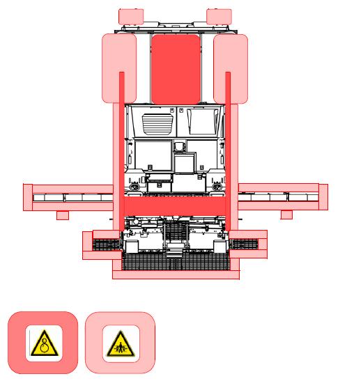
3. Danger zones
In the working areas around the machine (marked in red), there may be a risk of drawing in or crushing during normal operation caused by rotating and conveying elements, or by components in motion.
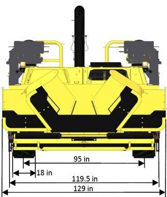
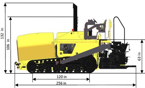
4 Technical data, standard configuration
4.1 Dimensions
For screed technical data, refer to the screed operating instructions.
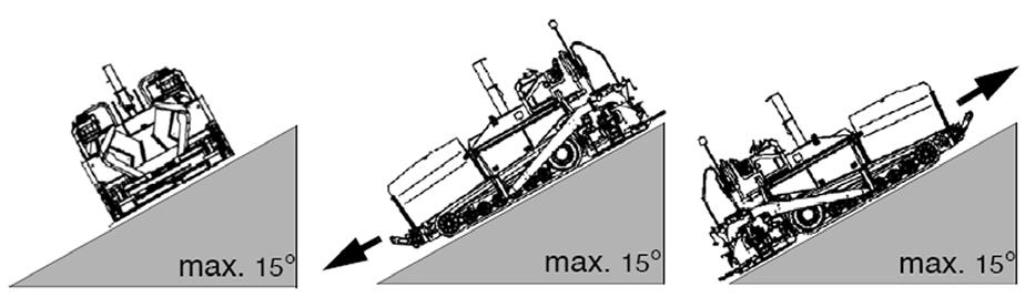
4.2 Allowed angle of rise and slope
Before operating your machine in an inclined position (gradient, slope, lateral inclination) which is above the specified limit value, please consult the customer service department for your machine!
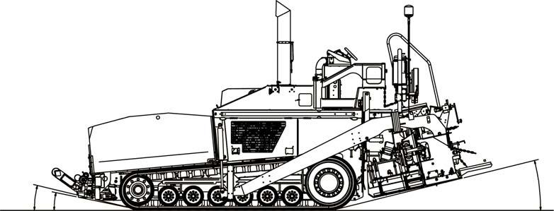
4.3 Permissible approach angle
4.4 Weights, F1000T
Paver without screed approx. 35,300 lbs. (16012 kg) Paver with screed:
- Carlsson EZ IV 1019 (7000 lbs) approx. 42300 lbs. (19187 kg)
- Carlsson EZ III 10 (6000 lbs) approx. 41300 lbs. (18598 kg)
- Carlsson EZR 10 (8250 lbs) approx. 43550 lbs. (19754 kg) With filled hopper, include an additional maximum of: approx. 30000 lbs. (13608 kg)
4.5 Performance data
4.6 Engine
Make/type Cummins QSB-6.7 Tier IV Final Version 6-cylinder diesel engine (water-cooled)
Performance
Fuel tank capacity
4.7 Hydraulic system
Hydraulic pressure supply source
222 hp @ 1800rpm
225 hp @ 2000rpm
2 tanks, 49 Gal (185 lt) each.
Pressure distribution
4.8 Material compartment (hopper)
Hydraulic pumps via distribution gear (directly flanged to the engine)
Hydraulic circuits for:
- Propel system
- Auger drive system
- Works system (conveyor, hydraulic cylinders)
- Generator system
- Vibration system approx. 235ft3 (6.65m3) Dumping height, center / outside 16 in (406mm) / 27 in (686m3)
4.9 Electrical system
4.10 Operator stations
Dual swing out operation stations
4.11 Conveyors
Conveyor type
Conveyor control
Dual independent slat conveyor
Proportional speed control, both side driven independently
Auger control
4.13 Permissible temperature ranges
Dual independent proportional augers
For the capacities for the various lubricants and operating substances, see chapter F.
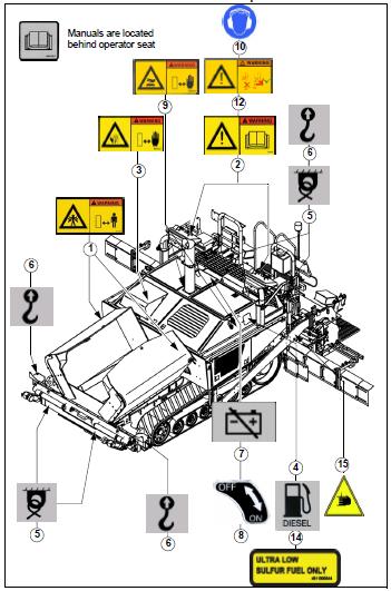
Description
Warning! Crush area!
Keep a safe distance when machine is running or moving. Do not work in this area when the machine turns or machine parts move!
Crushing can cause severe injury or death!
Warning! Do not work on this machine unless you have read and fully understand the warnings and instructions in the Operation/Maintenance and Safety Manual! Failure to follow the instructions or heed the warnings could result in injury or death. Contact your Dynapac dealer for replacement of manuals. Proper care is your personal responsibility!
Warning! Keep a safe distance from rotating fans! Do not work around or on the fan when fan is in operation!
Rotating fan blades can cause severe injury or death!
Filler neck for diesel fuel!
(Located on both sides of machine)
Tie-down points on machine!
(Located on both sides and front and back of the machine)
Lifting point on machine!
(Located on both sides and front and back of the machine)
Main battery switch location!
NOTE:
Follow instructions for using battery main switch!
ON/OFF positions for battery main switch. ON - battery connected OFF - battery disconnected
Warning! Hot parts or components can cause burns! Keep a safe distance!
Hot surface can cause burns or personal injury. Do not come into contact with hot parts or components. Wear protective clothing or protective equipment!
Wear ear protection when using the machine! Hearing damage could result from high noise level when ear protection is not used!
Warning! Do not drive the machine while standing! Severe injury or death from an unseated position could occur!
Always use seat and seatbelt when driving machine in transport gear!
Location of machine manuals on the machine.
Description
Ultra-low sulfur diesel only.
Warning! Crush area!
Keep a safe distance when machine is running or moving. Do not work in this area when the machine turns or machine parts move!
Crushing can cause severe injury or death!
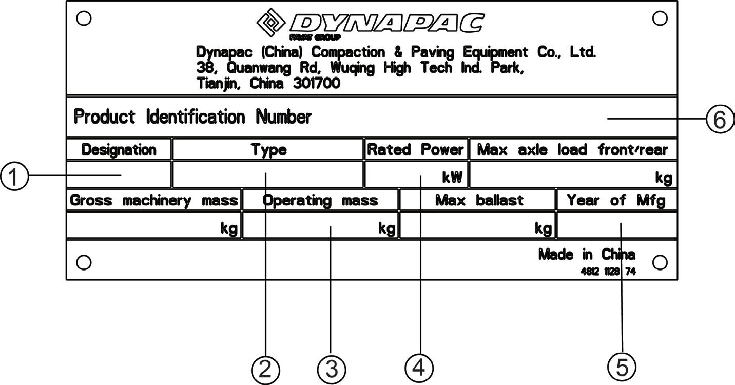
5.1 Identification plate for the paver finisher
Item Designation
1 Paver
2 Paver type
3 Mass of the base machine with all standard equipment kg
4 Paver rated power kW
5 Year of manufacturing
6 Product identification number (PIN)
The stamped vehicle identification number on the paver must match the product identification number.
6 EN standards
6.1 Continuous sound pressure level on the F1000T Track Paver, Cummins QSB 6.7 Tier IV Final Engine.
The operator always must use ear protection. The noise level at the operator’s ear varies depending on the materials used for paving and may even rise above 85 dB(A). If no ear protection devices are used, hearing can be impaired. The noise emission level of the paver was measured under free-field conditions ac- cording to the 2000/14/EC, and ISO 3744.
Sound pressure level at the operator’s position (at the height of the head):
6.2 Operating conditions during measurement
The diesel engine was running at 2000 rpm. The screed was in working position, lowered to a rubber mat. Vibration unit was operated at min. 50%, while the augers were operated at a minimum of 100% and the conveyors were operated at a minimum of 100% of their maximum speed.
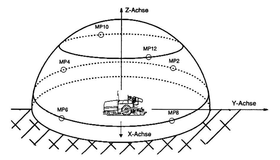
6.3 Measuring point configuration
Hemispherical measuring surface with a radius of 52.5 ft. (16 m). The machine was at the center. The measuring points had been assigned the following coordinates: Measuring points 2, 4, 6, 8 Measuring points 10, 12