11 minute read
BVehicle description

from Dynapac Cold Planer PL 2000 S PL 2000 LS Operating Instructions Manual 900981225 - PDF DOWNLOAD

1Description of usage
The DYNAPAC cold planer PL 2000 S/PL 2000 LS is a compact, efficient large planer, hydraulically driven by four steerable crawler units. It has a front loading system which is used to remove asphalt and cement layers. The milling drum transmission is driven mechanically by high strength V-belts.
As a result of its high milling performance, we would recommend that this cold planer is used in particular when carrying out extensive redevelopment work on large and spacious roads, such as motorways, urban and country roads, car parks, airports etc.
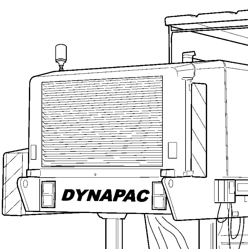
The PL 2000 S/PL 2000 LS corresponds to the European safety standard and satisfies very stringent requirements in terms of its reliability, economic viability and environmental responsibility. PL2000LS_front.wmf
2Descriptions of assemblies and functions
ItemDesignation
1Frame
2Operator’s control station
3Weather protecting sun roof
4Control panel
5Lower control panels
6Engine
7Air pressure system
8Belt drive (milling drum transmission)
9Milling section
10Traction units
11Strut towers
12Lower Conveyor
13Upper conveyor
14Water refilling system
15Water tank
16Video monitoring system
17Water spraying system
18Folding ladder
19Guardrails (on both sides)
20Plug-in contacts for additional headlight (on both sides)
21Storage area
22Swivel-mounted radiator grille
23Connection for external water filling (filling under pressure)
24Hinged warning sign
25Lane pointer
2.1Vehicle Assembly
Frame and assembly: Robust, distortion-resistant steel welded design with useful brackets for supporting the assemblies, units, attachments and tanks. All parts can be easily accessed for maintenance and repair work.
Operator’s control station: The continuous length of accessible operator’s control station is located in the central part of the machine and can be reached via two ladders. Two ergonomic seats ensure that the planer can be conveniently operated from both sides and that the operator has a good overview of and can monitor the milling process.
The cold planer can be fitted with a weather protecting sun roof (can be folded in) and all-round panels as an option. During transport, the roof can be folded forwards hydraulically and secured on the water tank.
Controls at operator’s control station: Two operating panels which contain all the controls needed are fitted to the right or left on the operator’s control station. These feature height adjustment and can be pulled out beyond the outer edge of the vehicle. The securely arranged controls are obviously marked for all applications. A clearly laid-out monitoring unit is fitted in the centre.
Steering and feed are simultaneously controlled using a drive lever, designed as a joystick. A second joystick controls the position of the upper conveyor and its speed (controlled in a gradual manner).
The main control panel, the lower control panels and access to all important switching and connection points can be sealed off.
Lower control panels: The operating panels housed here are located on neither side of the planer, in front of and behind the milling roller box. They contain duplicates of the main controls of the operator’s control station with override functions so that the milling process can be monitored, corrected and interrupted from this point.
One digital controller for the milling depth and one for the slope position are attached next to the rear operating panels on the left and right sides.
Engine: The machine is fitted with a powerful 6-cylinder Cummins turbo diesel engine which effortlessly covers the power requirements of the large planer. This engine has electronic engine management which also automatically adapts it to the extreme operating and environmental conditions and therefore keeps its torque stable. The emissions values specified by the U.S. EPA exhaust standard and the European exhaust standard, COM3, are observed. The engine cover is noise-insulated as standard so that operating staff and the surrounding area are subjected to minimum levels of noise.
Milling section: The milling section consists of the mechanical milling drum transmission, the milling drum housing, the milling drum, the moldboard, the sliding shoe and the side boards.
All these elements are precisely tuned to one another and their designs adapted so that a high milling performance is assured with low levels of bit wearing, as is very good retrieval, granulation and transport of the milled product, an exact milling pattern with cleaner milling edges is produced and the processed area is kept clean and free of milling product which has not been retrieved.
-The mechanical milling drum transmission is driven by the diesel engine via a hydraulic separating clutch, belt pulleys and a 14belt powered-belt pack on a planetary gear directly connected with the drum body. This guarantees a low-loss transfer of power, intercepts load impact and has a long service life. The drive is fitted with an automatic belt tensioning fixture. The hydraulically selectable 3-pulley dry-plate clutch and the two-stage planetary gear are configured specially for the milling drum transmissions and finely tuned to the engine rating of the machine.
-The milling drum rotates in the opposite direction to the machine forward drive. The professional bit arrangement and equipping with the best bits ensures rapid and clean cutting as well as high bit life.
A good, tried and tested, new type of quick change tool holder system is used on the standard drum. Thanks to the manner in which it is able to rapidly and simply replace upper fixing parts, it makes minimum change times possible and does not therefore cause long downtimes during replacement.
-The milling drum housing seals off the milling drums to the left and right through the side boards, the sliding shoe to the front, the moldboard to the rear, in all milling depths and therefore ensures optimum material pickup and a clean cutting surface. The side boards are fitted with replaceable, zero-wear hard metal plates to increase their service life.
Traction unit, steering system, brakes
- Traction unit
Four large crawler units, suspended in floating manner on the strut towers, hydrostatically driven and fitted with sensor-monitored anti-slip control are equipped with slipfree plastic pads. They provide excellent traction when cornering and in all usage positions.
Driving and working gear can be selected. The speed limits required can be set beforehand using the button provided or can be changed during operations. The control lever of the travel drive then allows the speed to be gradually adjusted in this driving range from zero to the maximum for both forwards and reverse travel. When overloaded, the machine feed is automatically reduced using limit load control.
-Steering system
The machine has fully-tracked steering and therefore has high manoeuvrability. When used in conjunction with a pre-selection button, the control lever allows the machine to be driven in four different steering variations and the speed to be changed at the same time:
-„only front-steered“,
-„only rear-steered“,
-„co-ordinated front and rear-steered“
-„driving in crab steering“
If necessary, both axes are brought into the straight ahead position at the touch of a button.
- Brakes: The machine is braked by the auto-inhibit of the hydrostatic drive and by the hydraulic spring accumulator brakes integrated in the gears of all four drive units. The machine is braked when the control lever is swivelled back from the maximum position to neutral. The accumulator spring brakes are activated both in the neutral position (during machine „Stop“) and when the engine is shut down and they act as parking brakes.
During a towing procedure, the spring accumulator brakes can be hydraulically disengaged by a manual pump.
- Strut towers: The strut towers are secured to the vehicle frame. The cold planer is lowered and raised in a controlled manner into the position required via these towers. The milling drum is therefore moved into the correct cutting position and compliance can be maintained with the milling depth and slope required during milling. The height of the strut towers is adjusted using an integrated hydraulic cylinder which is activated by proportional valves.
The milling depth and slope are set by means of the two front columns. The height of each of the front strut towers can be adjusted individually. The two rear columns operate in tandem and therefore adapt themselves to the appropriate machine position. For service purposes, the rear strut towers can also be changed over to individual adjustment mode.
The strut towers make a large lifting height possible so that the space required between the machine and ground is always provided during difficult manoeuvres such as loading.
Levelling equipment: The cold planer is fitted with electronic levelling equipment as standard. The levelling equipment consists of two digital controllers and LC display which can be connected with combination of a tilt sensor and various height or distance sensors.
The levelling equipment controls the cylinders of the front drive unit legs. The milling depth and lateral slope required are pre-selected and compliance is automatically maintained with them during milling as the distance defined to a reference surface is continually compared and corrected. The automatic operation can be briefly bridged and replaced by manual control. The levelling equipment cannot respond when not intended during a period of downtime because a safety cutout is engaged when the machine is stopped. In its standard version, the cold planer is fitted with two digital controllers and optionally either with two cable sensors acting on the side boards or two ultrasonic sensors for zero-contact sensing of the surface.
As an option, the machine can be fitted with an additional tilt sensor, either with ultrasonic sensors or laser receivers for zero-contact sensing or also with rotary sensors for contact sensing of tensioning cables and side panels.
Water system : The water system consists of the water spraying and cooling system and the cleaning system (O). It is operated by a hydraulically driven average pressure water pump.
-Water spraying and cooling system:
The water spray and cooling system (operating in the average pressure range) is used to cool and freely spray the bits, of the milling drum, lower and upper conveyor. The spray nozzles can be easily replaced.
-Cleaning system (optional):
As an extra, the cold planer can be fitted with a water lance and tube reeling device for cleaning operations. The system is operated in the average pressure range.
Water refilling system : The cold planer is fitted with two front and rear C-shaped pipe connections and a large filling aperture as standard for rapid water filling. As an option, a hydraulically driven recirculating pump which significantly reduces the filling time can also be used. The water tank is large and resistant to corrosion.
Loading unit: The cold planer is designed as a front loader and has a dual-section, wide-belt loading system. The lower conveyor located under the machine receives the material released and ejected by the milling drum and conveys it to the front upper conveyor.
Wide material transfer hoppers ensure a clean transfer. Via the upper conveyor, the milled product is finally loaded onto a means of transport or its support outside the milling lane. Both conveyors are wide and have conveyance speeds which can be set in both forward and reversing mode. Their maximum values can be pre-selected depending on the material in question. Here, the speed of the upper conveyor can be gradually adjusted from zero to maximum when in operation. The speed of the lower conveyor automatically changes in proportion to the speed adjustment of the upper conveyor.
All belt changes can be simply and rapidly performed. The lower conveyor is positioned on a sliding shoe to protect it from wear. This shoe also serves as a compression device and prevents lumps from breaking up on the cutting surface. Spraying the inside of the belt with water prevents it from sticking to the asphalt granulate
The hydraulically adjustable upper conveyor has a large loading height and can be swivelled a long way to each side. The level of dust contamination is noticeably reduced through the use of the complete cover available. As an option, the upper conveyor can be folded in for simpler transport.
Hydraulic system: The various operating functions of the cold planer are conducted using several, independent hydraulic circuits with a clear pipework system, predominantly permanently installed piping and short sections of hose connection. All hydraulic pumps are driven centrally by a pump drive in turn driven by the diesel engine.
To ensure that the entire hydraulic system is kept perfectly clean, a large return suction filter is fitted in the hydraulic oil tank for the drive circuits of the traction unit, loading conveyor, fan and water system. Two high-pressure filters can also be fitted as extras in the circuits for the cylinder actuator functions.
Electrical system: 24 volt system with two cold start high power batteries engaged sequentially and a 3-phase generator. The power supply can be interrupted to ground/earth by the battery’s main switch.
Air pressure system: Compressor driven directly by the engine with 20 litre/6.3 bar compressed air tank. A power take-off point is located under the rear section of the machine with quick-release coupling for external consumers (e.g. pneumatic hammer punch or rotary piledriver).
Optional equipment:
-Extended levelling equipment: a transverse slope sensor, a digital rotary arm sensor, the ultrasound Sonic-Ski and laser receivers are contained in this package. In addition to this, a Roadscanner System can be used in conjunction with a transverse slope sensor.
-Fine spaced milling drum: milling width 2010 mm, with welded on lug boxes which can be positioned, line spacing 7.5 mm
-Milling section for 2100 mm milling width with normal or fine spaced milling drum,
-Upper conveyor with folding option: can be mechanically folded in downwards
-Weather protecting sun roof: can be mechanically or hydraulically lowered, with allround weather protecting panel (can be folded in) and electrical windscreen wiper.
-Additional operating panel: for the machine to be operated from both sides of the operator’s control station at the same time.
- Emergency operating equipment: can be used if the main operating panel fails
- Dust suction system: extraction and filtering of dusts and harmful vapours in the following areas: milling section, material transfer point between the lower and upper conveyor and discharge area on upper conveyor
-Water refilling pump by means of auto-suction recirculating pump driven by hydraulic motor, displacement quantity approx. 18m3 /h
-High pressure cleaner: water lance with approx. 13 m hosing, tube reeling device, operating pressure 130 bar, water consumption approx. 38 l/min
-Pneumatic hammer punch: bit set in toolbox, working pressure 6.3 bar, air consumption approx. 460 l/min, number of impacts 3000 p/min.
-Pneumatic piledriver: socket wrench set and extension in toolbox, working pressure 6.3 bar, air consumption approx. 580 l/min, torque 640 Nm.
-Compressed air pistol: for precision cleaning of areas difficult to access, working pressure can be adjusted between 2 -10 bar.
-Pneumatic grease press: with flexible compressed air hose, working pressure max. 8 bar, compression 480 bar (60:1)
-Spiral compressed air line: 10m in length for connecting compressed air tools
Other useful extensions and attachments are available on request.
3Safety devices
The machine can only be safely operated if the control and safety devices are functioning perfectly and if the protective equipment is fitted correctly.
The function of these devices must be checked regularly (refer to Chapter D, Section „Checklists for the machine operator“).
Emergency-stop button
-on both upper control panels -on all lower control panels
The engine, drives and steering system are shut down when the emergencystop button is pressed. Any countermeasures required (diverting, lifting the upper conveyor etc.) are then no longer available! Risk of accident!
The emergency-stop button must not usually be used to shut down the engine and should only be pressed in an emergency or for test purposes.
The traction unit brakes are applied whenever an emergency stop button is pressed!
Horn
-on both upper control panels on both control levers
-on all lower control panels
Before starting to operate the machine and moving the conveyor units, the horn knob and/or the horn button should be pressed to issue a warning signal.
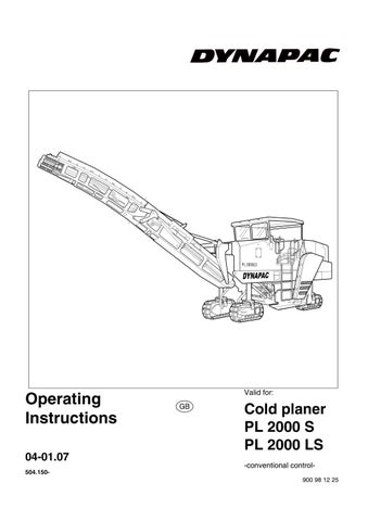
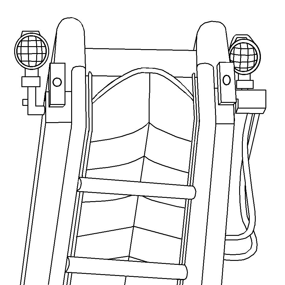
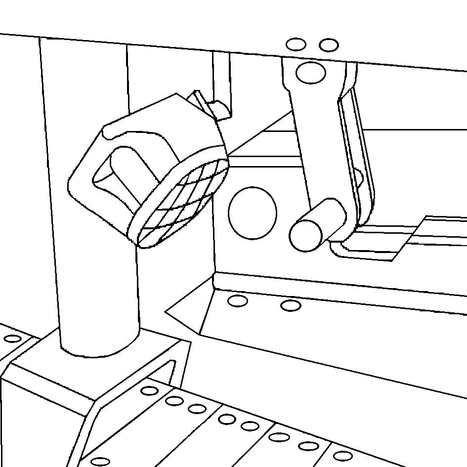
Headlights, indicators rotary beacons
Lights for illuminating different operating areas and for indicating danger areas and/or dangerous situations are located at various machine positions.
Several contacts, to which headlights can be connected, can be found around the machine.
The headlights, indicators and rotary beacons can be activated using the appropriate switches on the upper control panel.
The function of the headlights and warning lamps should be checked on a daily basis before starting work.
The headlights can be simply removed and should be taken off from the easily accessible points and safely stored once work is complete.
Headlight contacts which are not used should be protected using rubber caps.
Tanklight_LS.wmf//423Bel.Tif/422Bel.Tif
Hazard warning lights on side boards (O)
One hazard warning light can be found above the side board on both the left and right-hand sides of the machine. The hazard warning lights are operated as soon as the side boards are raised.
Reverse lights and folding warning signs, reverse warning device
The reverse lights illuminate the danger area behind the machine. A warning sign can be folded out on the right-hand side of the machine and is used e.g. to warn any traffic behind the machine.
A reflective film is fitted to the other side of the back of the machine.
The machine is also fitted with an acoustic reverse warning device which sounds as soon as the machine starts to reverse.