2 minute read
Assembling/dismantling the universal drive shaft protection


16
1
3
2
Danger!
Work on the drive shaft may only be carried out with the PTO disengaged and the engine switched off. – Remove the ignition key. Never operate the drive shaft without or with damaged guards. – Mount the joint guards and protective tubes. – Secure the guards against rotation. – Only use drive shafts that are in
perfect technical condition.
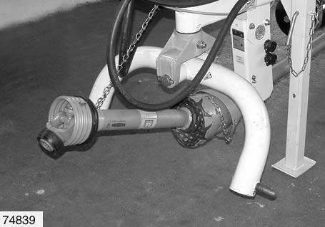
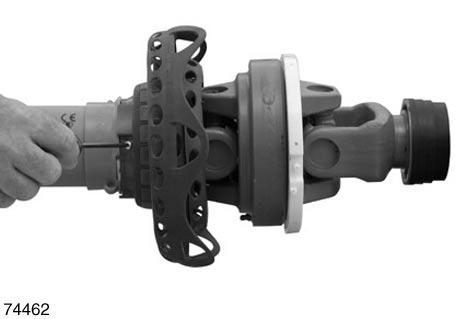
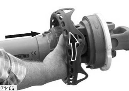
In order to remove the universal drive shaft and for greasing the joints, sliding surfaces and protection tubes, the universal drive shaft protection must be removed. For lubrication intervals and lubricant specification –see Lubricating chart, page177. (Fig.16)
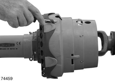
Proceed as follows for removal of the universal drive shaft protection: • Use a tool (e.g. a screwdriver) to release the sleeve(2) from the protective funnel(1). • Remove the fixing screws(3) (6x). (Fig.17)
18
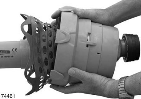
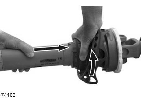
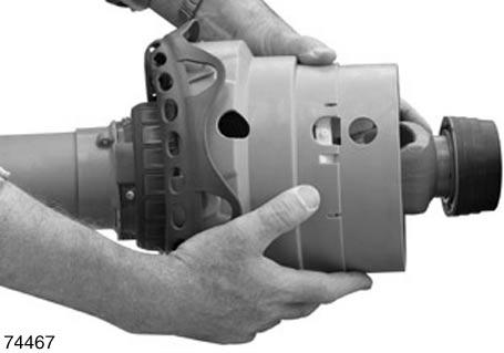
• Pull the protective funnel off. (Fig.18)
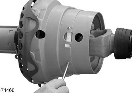
• Remove the stop screws(4) (3x). (Fig.19)
4
19
20
2
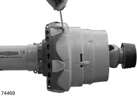
• Turn the sleeve into the mounting position (up to the perceptible stop). (Fig.20)
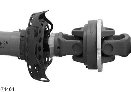
• Pull the sleeve(2) off. (Fig.21)
21
5 6
5
7 6
7
2
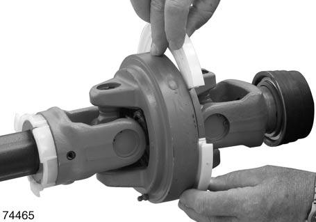
• Remove the slide rings(5,6). (Fig.22)
22
Proceed as follows for fitting the universal drive shaft protection: • Grease the running grooves(7) of the slide rings. • Fit the slide rings(5,6). The cut-outs in the small slide ring(5) point to the profile tube. (Fig.23)
23
• Push the sleeve(2) into position. (Fig.24)
24
25
• Turn the sleeve into the locking position (up to the perceptible stop). (Fig.25)
• Fit the stop screws(4) (3x). (Fig.26)
4
26
• Push the protection funnel on and position the projections so that the screw holes(8) are visible in the cut-outs(8). (Fig.27)
8
3 27
• Fit the mounting screws(3) (6x). (Fig.28)
28
29
• Use a tool (e.g. screwdriver) to mount the sleeve onto the protective funnel. (Fig.29)