4 minute read
Using the machine with ISOBUS Terminal


Swather with ISOBUS Terminal
4 13.1.1Using the machine with ISOBUS Terminal
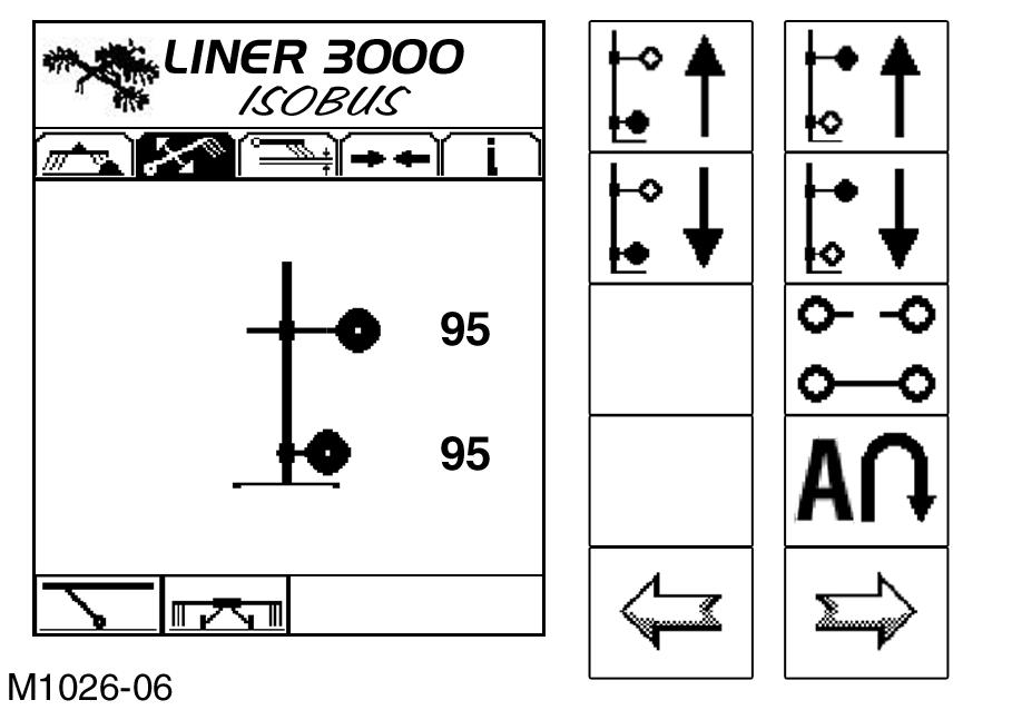
Adjusting the working width (rotor overlap)
The working width of the swather can be adjusted by means of the front rotors. If the working width is increased, the overlap between the front and rear rotors is reduced, and if the working width is reduced, the overlap is increased.
There are several screens in which the working width can be changed. Use the following soft keys: Soft key “Increase working width”.
Soft key “Reduce working width”.
Press the corresponding soft keys until the desired working width has been reached.
Caution!
Do not adjust to less than the minimum working width –see Minimum working width, page125.
5
6
Swather with ISOBUS Terminal
Swather with ISOBUS Terminal 7
8
9
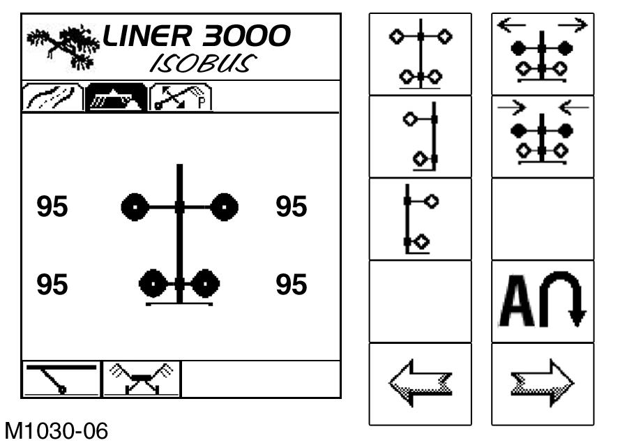
The working width can also be set in the “Working Width” tab. See Figs.7 and 8 for the relevant screens. The menu bar shows the “Working Width” icon inverted. See chapter Working with individual rotors, page129 (Fig.17,18,19) for a description of how to call the screens. Always keep the overlap large enough for the crop to be completely collected even when turning.
(Fig.4,5,6,7,8)
Note!
The newly adjusted working width is stored. After automatic approach of the working position from the transport position, the max. working width is reset. A smaller working width must be adjusted again.
Raising/lowering the rotors to the headland position
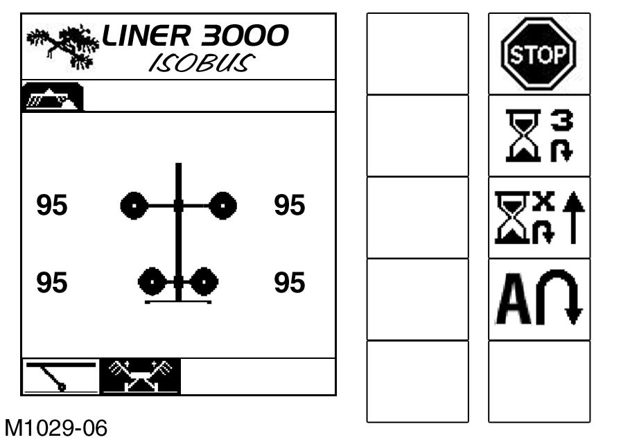
The headland position can be adjusted from several different screens. The function is available as soon as the soft key is displayed. Fig.9 shows the “Working Position” screen. Press this “Soft Key” to raise the rotors at the headland. – The control unit first raises the front rotors, and then the rear rotors. The delay depends on the adjusted delay time –see Adjusting the headland settings, page85.
10
11
Swather with ISOBUS Terminal
12
– The display switches to the “Headland up” screen (Fig.11).
Note!
If the soft key is pressed again before the headland position is reached, the rotors are lowered to the working position immediately.
When the headland position has been reached, the display changes to “Headland adjusted” (Fig.12). Press the “Soft Key” again to lower the rotors. The control unit now lowers the front rotors to the working position, and then the rear rotors. The delay depends on the adjusted delay time –see Adjusting the headland settings, page85.
The operator can switch between the two functions as desired without reaching the full headland height or working position.
Note!
If the soft key is pressed again before the working position is reached, the rotors are raised to the headland position immediately.
Note!
It is not necessary for the PTO shaft to be disengaged at the headland.
13
Swather with ISOBUS Terminal
14
When the working position has been reached, the display changes to “Working Position” (Fig.14). (Fig.9,10,11,12,13,14)
Swather with ISOBUS Terminal
Swather with ISOBUS Terminal 15
16
17
Swather with ISOBUS Terminal
18 Working with individual rotors
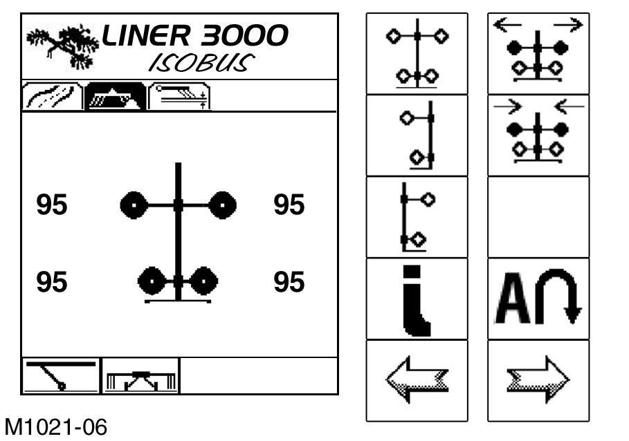
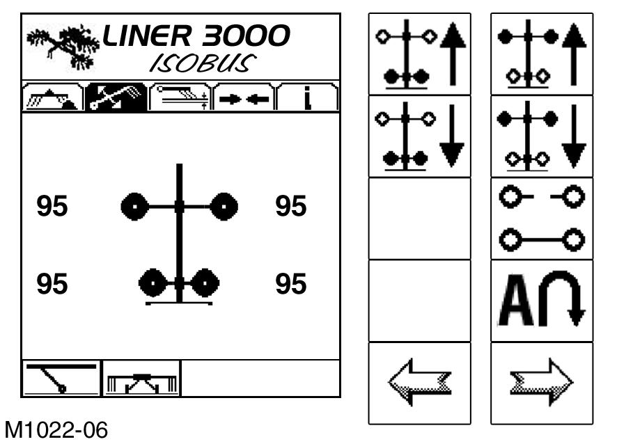
When working narrow or tight areas, the operator has the option of working with only one rotor or with several rotors, by using the individual raising function. Any rotor can be selected for working. The rotors can be adjusted singly or in pairs, if the following soft keys are available. The following soft keys are available in the “Working Position” (Fig.15) or “Headland reached” (Fig.16) screens: Rotors on both sides
Rotor on one side left
Rotor on one side right
By pressing the “Soft Key”, the display changes to the screen “Raise both sides” (Fig.17). In this screen, the rotors can be raised and lowered in pairs. Pressing the soft key “Rotor one side left/right” also switches the screen, similarly to pressing the soft key “Selecting rotor controller”.
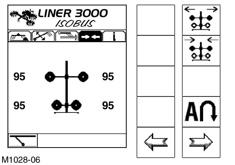
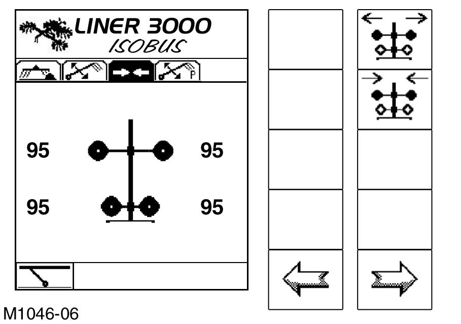
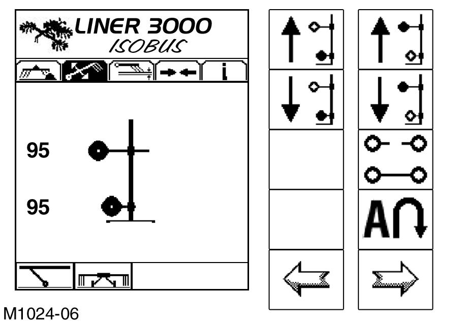
Soft key “Selecting rotor controller”
Soft key “Selecting rotor controller”, left/right or both sides. Pressing the soft key switches the program to the next screen; this means: “Single control left” screen (Fig.18) --> “Single control right” screen (Fig.19)--> “Both sides front or rear” screen (Fig.17)--> “Single control left” screen, etc. Use the soft keys to raise or lower the corresponding rotors individually or in pairs.
Note!
The raising height is limited to the maximum headland height here. Simply pressing the soft key briefly is enough to lower the rotors (push-button function). To raise the rotors, press the soft key until the required position is reached. The operator can simply switch between the functions without having to reach the end position (toggle function).
19
20 Overview of “single actuation” soft keys
Soft key “Lift left front rotor”
Soft key “Lower left front rotor”
Soft key “Lift left rear rotor”
Soft key “Lower left rear rotor”
Soft key “Raise the right front rotor”
Soft key “Lower the right front rotor”
Soft key “Raise the right rear rotor”
Soft key “Lower the right rear rotor”
Soft key “Raise the front rotor pair”
Soft key “Lower the front rotor pair”
Soft key “Raise the rear rotor pair”
Soft key “Lower the rear rotor pair” (Fig.15,16,17,18,19,20)
Note!
If the machine is fitted with hydraulic rake height adjustment, the rake height is adjusted in a similar way as described for the previous versions. For further information see page 138.