2 minute read
9.6. Working position with ISOBUS Terminal


71494
P
26 9.6 Working position with ISOBUS Terminal
Danger!
When raising/lowering the rotors, make sure that nobody is in the pivoting area. There is a risk of injury. – Direct all persons out of the danger area. – Switch off the machine at once, if necessary. – If necessary, interrupt the control unit with the “STOP” key. Never work on the machine while the tractor's engine is running. – Switch off the engine. – Remove the ignition key.
• Preparatory procedures –see Before lowering into the working position, page57.
Attention!
Blocked wheels on the swather can lead to damage of the swather's running gear, because the running gear cannot be swivelled. – Release parking brake on the tractor and on the rotary swather. – Do not operate foot brake.
• Never actuate the foot brake and/or the parking brake while extending or retracting the outriggers. • If necessary secure the tractor with wheel chocks to prevent it from rolling. • Release foot brake and parking brake. (Fig.26)
Note!
For further information see the operator's manual of the terminal being used, or Operation –CLAAS Communicator, page67. The symbols are explained in chapter 11 Operation – ISOBUS Terminal from page 75.
• Before switching on the control unit, the hydraulic system must be pressurized.
27
28
29
• Turn the terminal on.
See the operator's manual of the terminal being used or Switching on/off the CLAAS Communicator, see page69. Press the “Soft Key”.
(Fig.27)
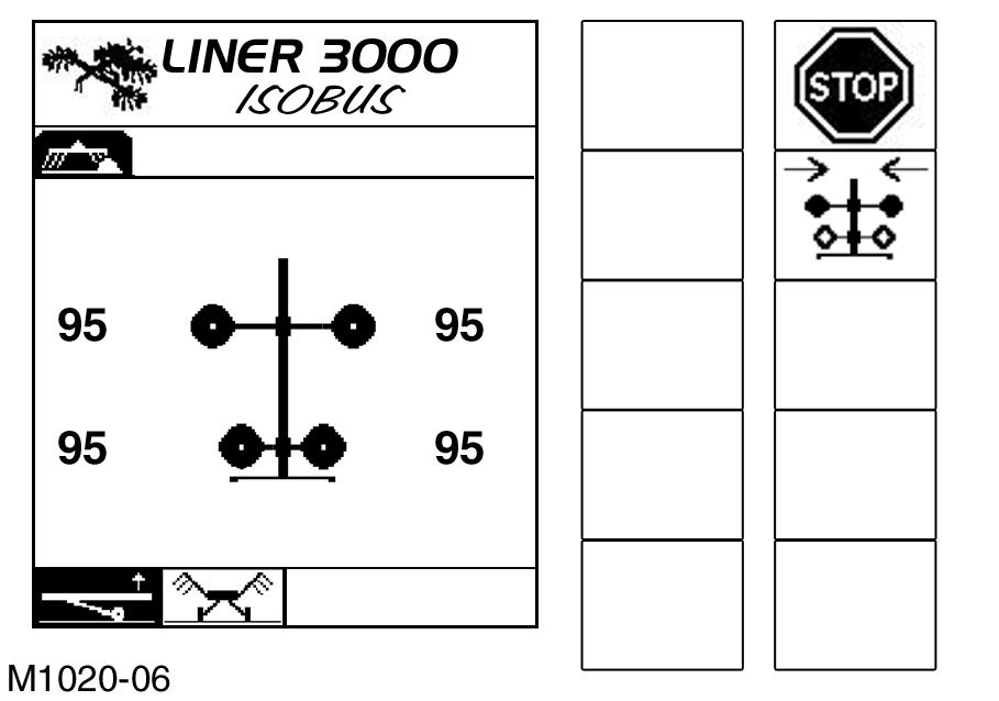
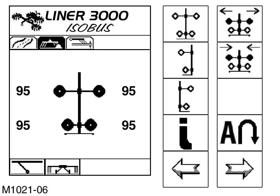
– The display switches to the “LINER3000” start screen. The submenu “Working Position” is active –the icon “Working Position” is shown inverted (Fig.28). Press the “Soft Key” (Fig.28).
– The machine is automatically adjusted to the working position (max. working width).
–The display switches to the “automatically approach working position” screen (Fig.29). –The running gear is raised. –The rotors are lowered. –After reaching the max. clearance height at the headland, the working width starts to increase.
Press the “Soft Key” (Fig.29).
– By pushing the soft key, the automatic expansion of the working width when lowering the rotors into the working position is stopped. – The working width can only be changed again in the “Working Position” screen (Fig.30).
Note!
The automatic sequence can only be interrupted by means of the “STOP” key.
Caution!
Do not adjust to less than the minimum working width –see Minimum working width, page125.
30
– When the working position has been reached, the display changes to “Working Position” (Fig.30).
(Fig.28,29,30,31)
Note!
The newly set working width is retained. After automatic approach of the working position from the transport position, the max. working width is reset. A smaller working width must be set again.
Caution!
Do not engage the PTO shaft before the machine has reached at least the headland position.
For further procedures –see Before starting field operation, page64.