3 minute read
Tensioning cylinders for upper and lower arms

from CLAAS COMBINE VARIANT 260 VARIANT280 ADJUSTING THE ENDLESS BELTS Assembly instructions Manual_DE_EN_

TENSIONING CYLINDERS FOR UPPER AND LOWER ARMS
Recommendations
For the following tests with recommend the use of a tractor with the following features: –Oil supply capacity: 50 l/min, –Oil temperature: 50 °C
Preparing the machine
Danger!
Before starting work in the hydraulic system shut the engine down, pull out the ignition key and block the machine against rolling. Relieve the pressure in the hydraulic system.
Environment!
Dispose of hydraulic oil acc. to applicable legal regulations.
General cylinder inspection
Check the function of the pressure gauge at the front of the machine.
1 3
2 4 5
6 5 4 3
2
1
A B 1
2
3 Test ports
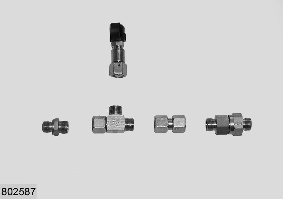
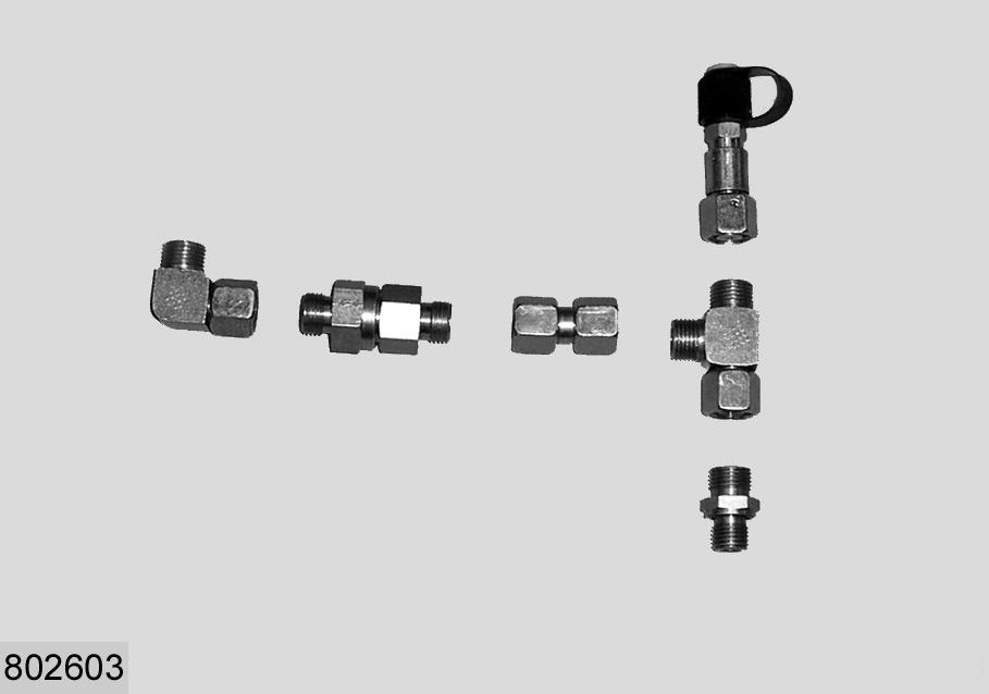
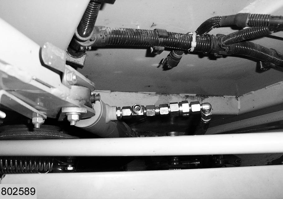
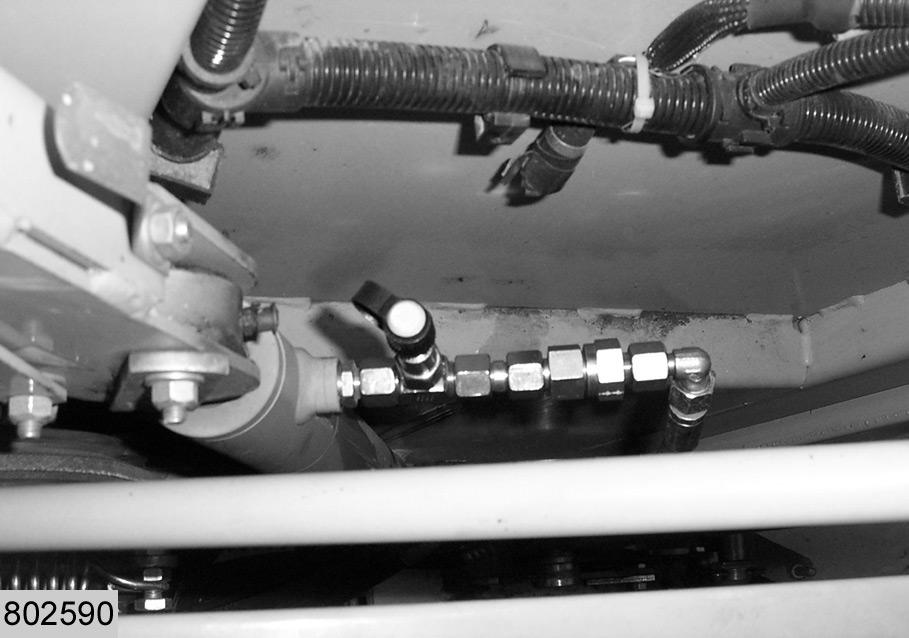
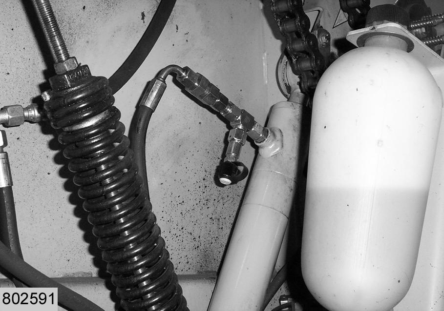
Use a Minimess pressure gauge (min. 0 - 250 bar) for pressure tests in the hydraulic system. Use the connecting set to test the cylinders for upper and lower arm. –Fig. 1 shows the set for the lower arm. –Fig. 2 shows the set for the upper arm. (Fig.1,2)
Part-numbers for the connections used:
Pos. No.
Spare part Designation 1 238 712.0 Straight fitting DIN901 2 238 890.0 Connection 3 683 656.1 Minimess 4 216 093.0 Connection 5 239 112.0 Check valve 6 238 693.0 Connection L 10
Attention!
Always install check valve (5) the right way around (direction of arrow)!
Lower arm
Remove hydraulic hose (B) from the tensioning cylinder for the lower arm on the right hand side. Remove check valve (A).
Note!
Check valve (A) is not compatible with the connection set for pressure testing.
(Fig.3)
1 2 4 5 B
3
3
3 C 4
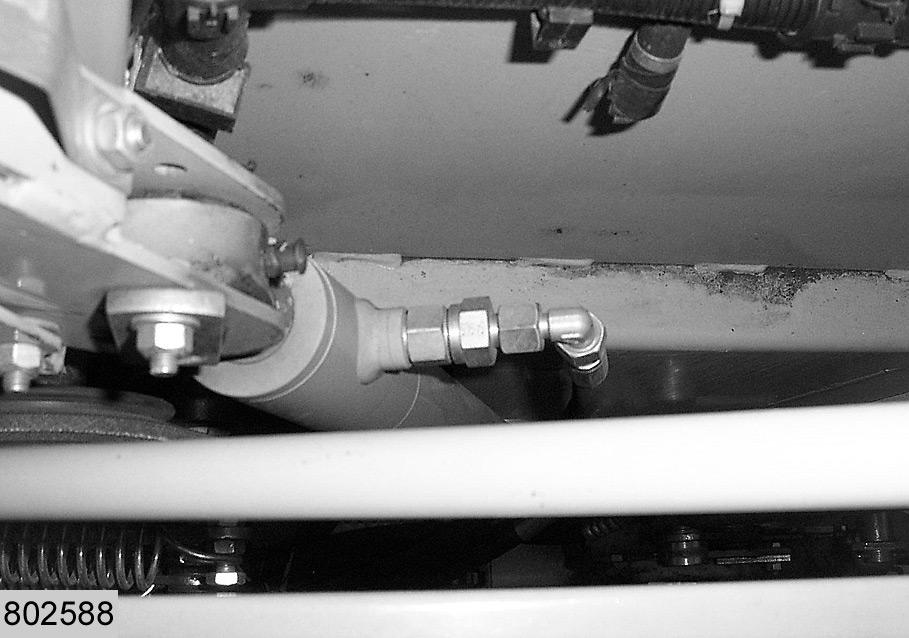
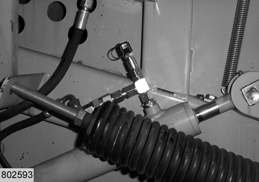
Pre-assemble connections (2), (4) and check valve (5).
Note!
Check whether check valve (5) has been installed the right way around (direction of arrow) and is correctly tightened.
Screw straight fitting (1) onto the cylinder. Fit the pre-assembled unit to straight fitting (1). Connect hose (B) to this unit. (Fig.4) Connect Minimess port (3) to the connection unit. (Fig.5)
Assemble the connection kit on the right hand cylinder of the lower arm in the same way. (Fig.6)
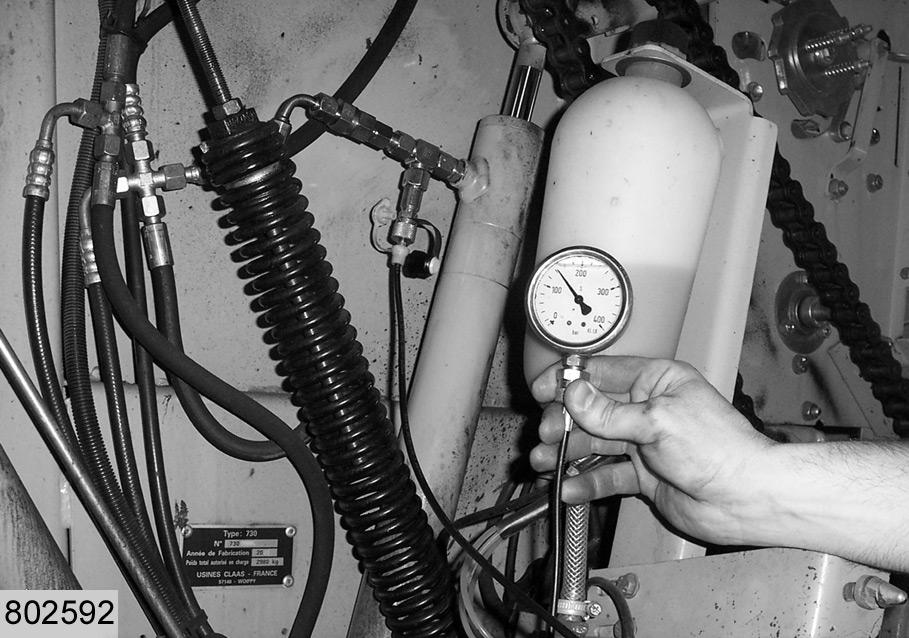
Connect electric and hydraulic systems of the baler to a tractor. Connect Minimess pressure gauge (C) to Minimess port (3) of the cylinder on the right hand side. Check whether the control terminal is switched off. Open the tailgate hydraulically by means of the tractor mounted control valve. Record the reading of the pressure gauge.
5
6
7
3
8 Note!
The pressure indicated by pressure gauge (C) (when opening the tailgate) must be identical with the pressure indicated by the gauge on the front of the machine.
–If the pressure reaches 180-200 bar, there is no internal leakage in the cylinder. –If the pressure drops, the cylinder is leaking:
Check cylinder seals and check valve for piston.
Replace defective parts (see spare parts list). (Fig.7) Repeat the test to check the leak tightness of the cylinder once again. Repeat this process to test the cylinder on the left hand side of the machine.
Upper arm
Connect the connecting set to the outlet of the cylinder for the upper tensioning arm (see Fig. 2). Connect electric and hydraulic systems of the baler to a tractor. Connect Minimess pressure gauge (C) to Minimess port (3) of the cylinder for the upper arm. Check whether the control terminal is switched off. Open the tailgate hydraulically by means of the tractor mounted control valve. Record the reading of the pressure gauge.
Note!
The pressure indicated by pressure gauge (C) must be identical with the pressure indicated by the gauge on the front of the machine.
–If the pressure reaches 180-200 bar, there is no internal leakage in the cylinder. –If the pressure drops, the cylinder is leaking:
Check cylinder seals and check valve for piston.
Replace defective parts (see spare parts list). (Fig.2,8) Repeat the test to check the leak tightness of the cylinder once again.