2 minute read
4. Initial position – tailgate open

from CLAAS COMBINE VARIANT 260 VARIANT280 ADJUSTING THE ENDLESS BELTS Assembly instructions Manual_DE_EN_

E
D D
Advertisement
F
G D 6 4. INITIAL POSITION – TAILGATE OPEN
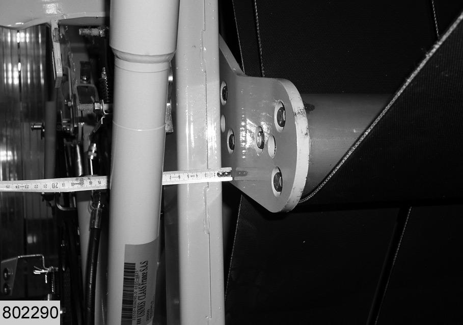
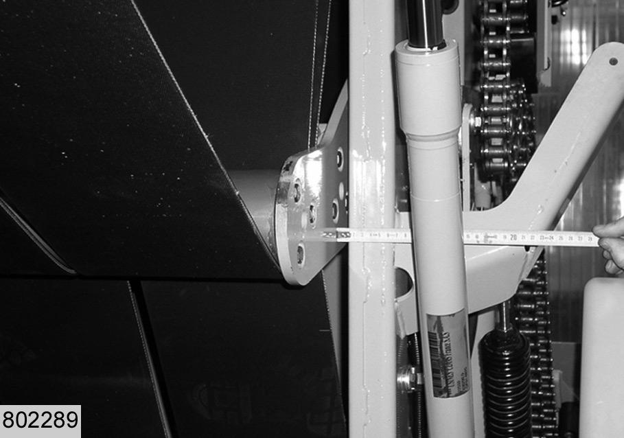
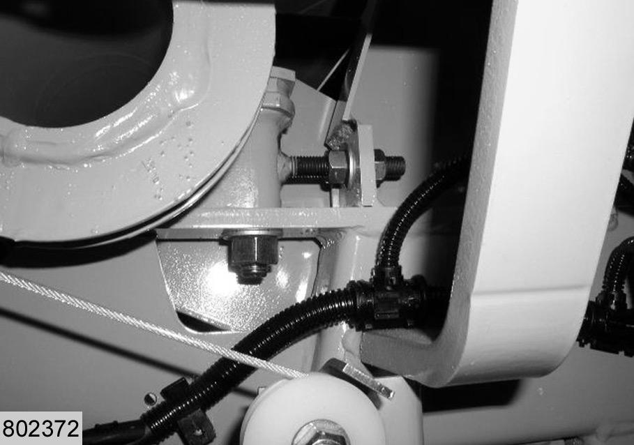
4.1 Clearance between wall and lower arm
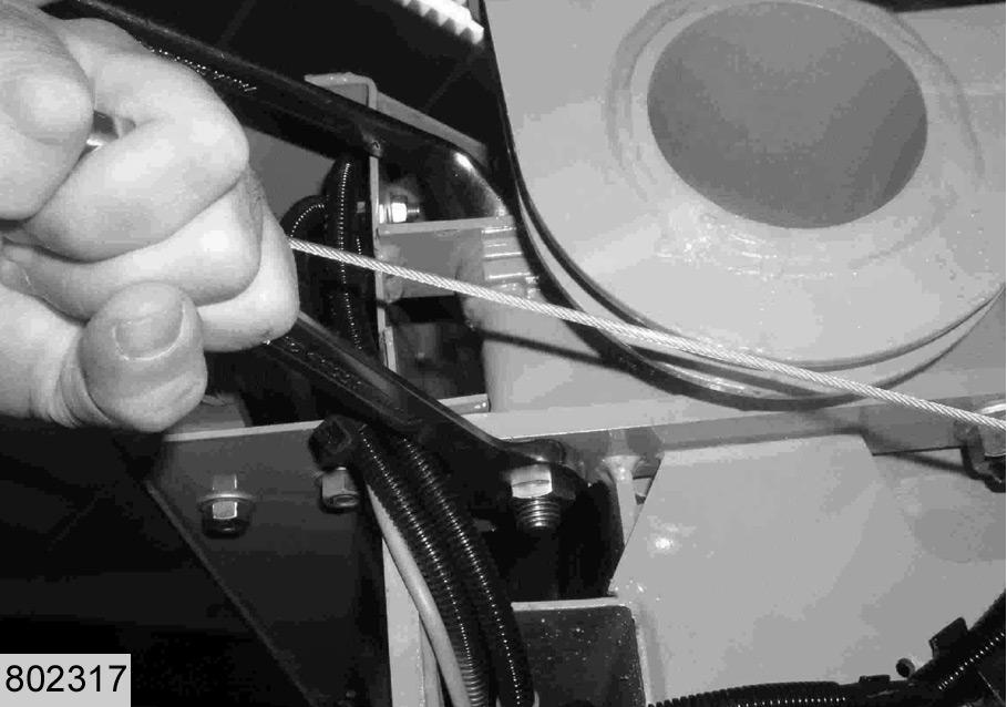
Measure the clearance between left (E) and right (F) hand wall and lower arm (D). The clearance between arm and walls must be at least 3 mm. If the clearance is less than 3 mm the lower arm needs to be adjusted accordingly. See item "4.4 Longitudinal adjustment of lower arm". (Fig.6,7)
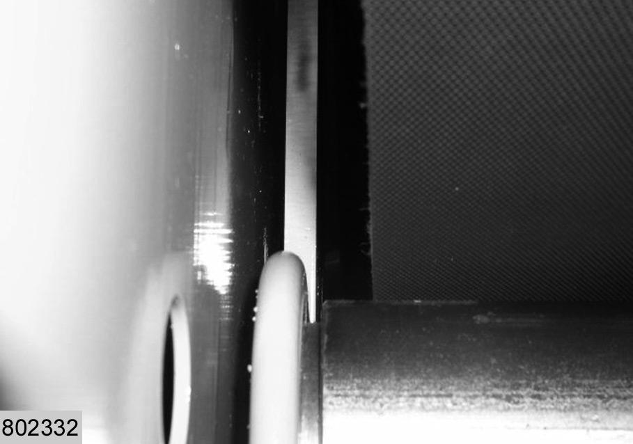
4.2 Aligning upper and lower arms
Check whether lower (D) and upper (G) arms are in line: the arms must overlap over a width of at least 8mm. –After aligning the arms continue with item "5.1Close the tailgate". –If the arms are not in line continue with following steps.
7
8 Note!
The lower arm effects the belt guide when the tailgate is open. The upper arm effects the belt guide when the tailgate is closed.
(Fig.8)
4.3 Relieving the belts
Relieve the belts hydraulic in order to be able to perform the following step. (see operating instructions, chapter on maintenance)
K H
D
Q D
J 4.4 Longitudinal adjustment of lower arm
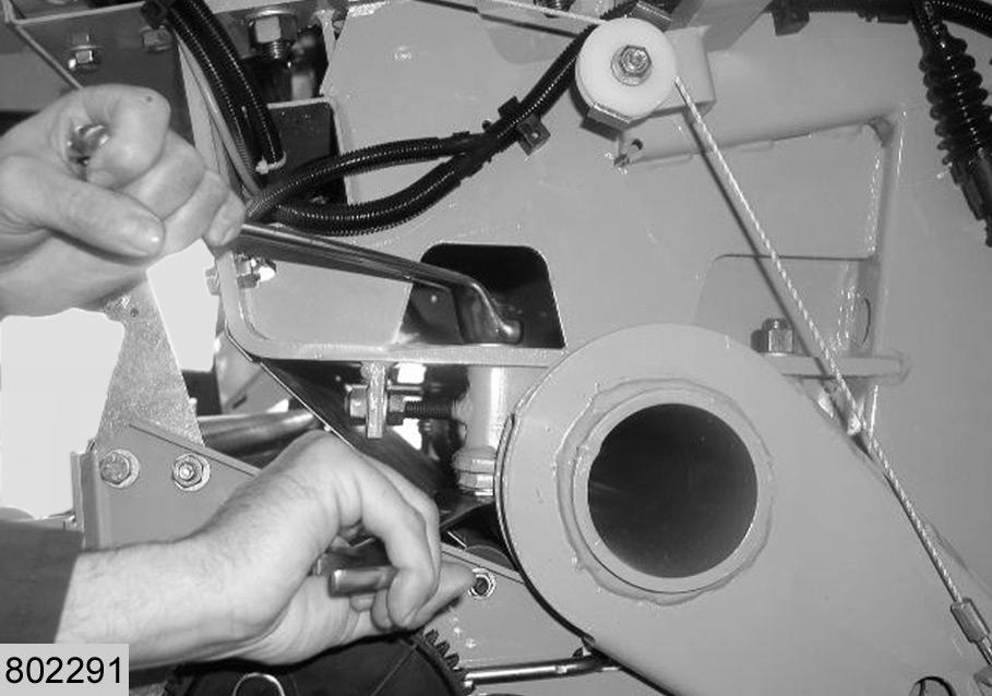
Loosen 4 fastening screws M16 (H) (right and left) on the lower arm (D). Align bolts (H) centrally in the slots. (Fig.9)
9
10
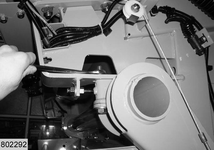
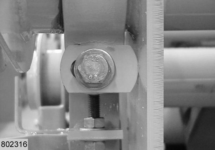
Adjust the lower arm on the front left hand side of the machine with threaded pin (K). –If the clearance measured under item "4.1 Clearance between wall and lower arm" on the left hand side was too small, push the left hand tensioning arm back. –If the clearance measured under item "4.1 Clearance between wall and lower arm" on the right hand side was too small, push the right hand tensioning arm forward. With this step the results obtained under item "4.1 Clearance between wall and lower arm" can be checked and corrected. (Fig.10) Tighten 4 bolts M16 and check the position of the adjustable stops (Q) during this procedure: –There must be a minimal clearance between the adjustable stops and arm (D): arm and stop must not touch. (Fig.11)
11
4.5 Longitudinal adjustment of upper arm
Loosen 4 fastening screws M16 (J) (right and left) on the upper arm. Align the bolts centrally in the slots. (Fig.9)
12
L
Q G
Adjust the upper arm on the front left hand side of the machine with threaded pin (L). –If the two arms were not in line under item "4.2
Aligning upper and lower arms", push the left hand tensioning arm back or forward, as required. (Fig.13)
Tighten 4 bolts M16 and check the position of the adjustable stops (Q) during this procedure: –There must be a minimal clearance between the adjustable stops and arm (G): arm and stop must not touch. (Fig.14)
13
14
4.6 Tensioning the belts
Tension the belts before conducting the following steps.