BI115525
(
NOTE: The bearings are press/it to the shaft and will require a puller to remove them.
NOTE: The bearings are press fit to the. shaft and will require a puller to remove them.
14. To remove the intermediate shaft (figure 9), remove the end cover at the pinion end of the shaft. Remove t.he O-ring from the end cover. Remove the bearing cap from the pinion end of the shaft.
17. Remove the bearing inner retainer from the' pinion end of the shaft. Remove the seal retainer and oil seal from the inner retainer.
15. With the overhead crane, lift the intermediate shaft from the gearcase.
18. Remove the bearing inner retainer and seal retainer from the gear end of the shaft. Remove the oil seal from the retainer.
NOTE: The drum and drum gear must be free to rotate to allow shaft removal.
NOTE: On some machines the inner retainer, seal retainer, and oil seal are replaced by a spacer.
16. Remove the bearing retainers from each end of the shaft and remove the bearings.
19. Remove the gear and key from the intermediate shaft.
(
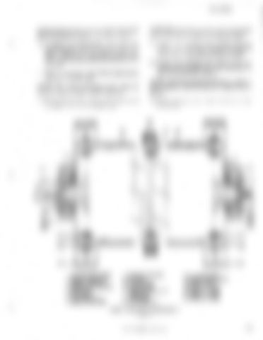
1. 2. 3. 4. 5. 6. 7. 8.
ROTARY LIMIT SWITCH SELSYN GENERATOR SWITCH COUPLING GENERATOR COUPLING END COVER END COVER LABYRINTH SEAL BEARING RETAINER
9. 10. 11. 12. 13.
BEARING RETAINER BEARING BEARING CAP DRUM SPIDER GEAR AND SPIDER TO DRUM BOLT 14. DRUM GEAR 15. R.H. DRUM HALF
16. 17. 18. 19. 20. 21. 22.
L. H. DRUM HALF DRUM TO .DRUM BOLT ROPE CLAMP HOIST L. H. BASE HOIST R. H. BASE DRAG L. H. BASE DRAG R. H. BASE
HOIST AND DRAG DRUM SHAFT FIGURE 10
" BUCYRUS-ERIE COMPANY, 1984
15


