2 minute read
WEDGE


4
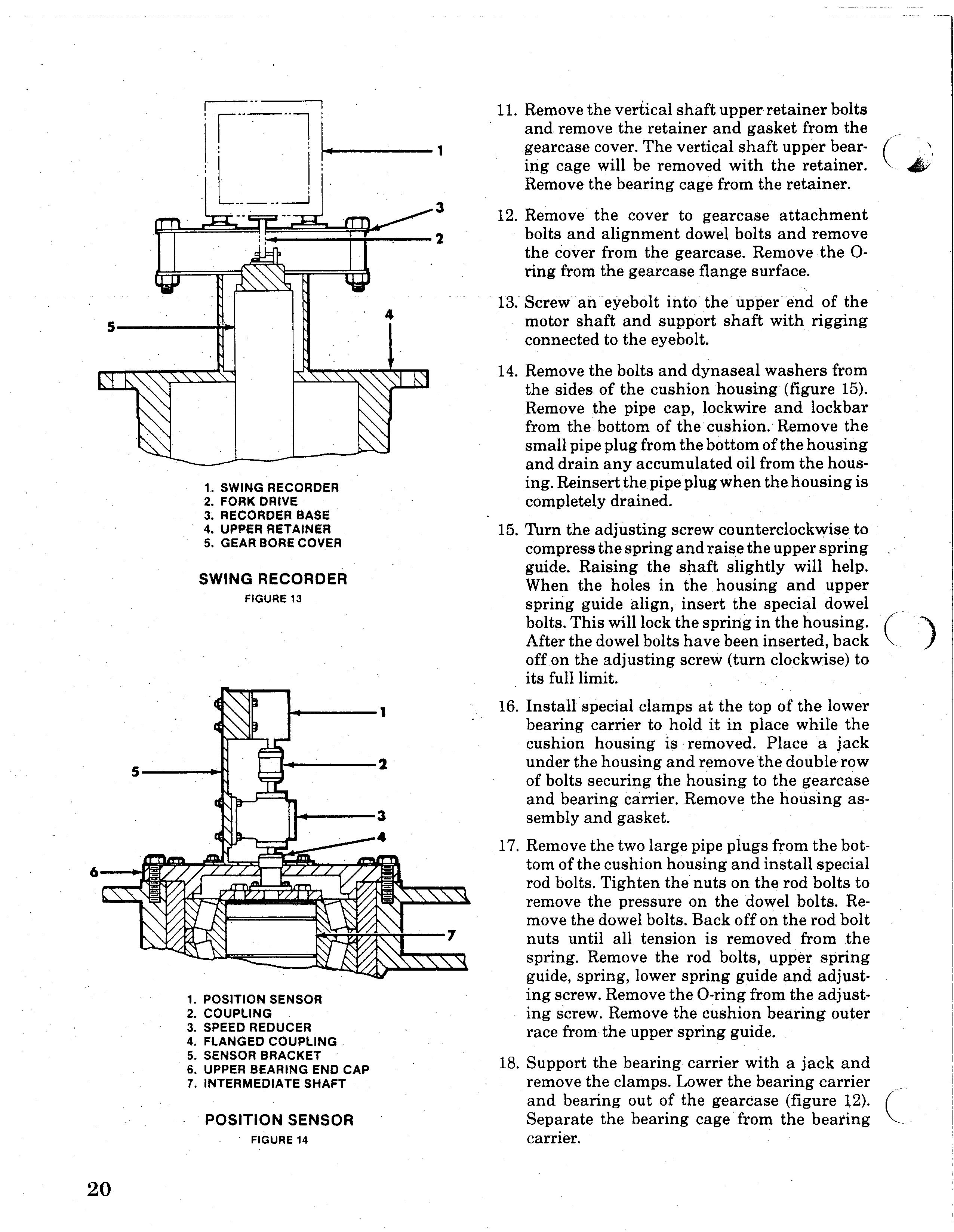
t. SWING RECORDER 2. FORK DRIVE 3. RECORDER BASE 4. UPPER RETAINER 5. GEAR BORE COVER
SWING RECORDER
FIGURE 13
1. POSITION SENSOR 2. COUPLING 3. SPEED REDUCER 4. FLANGED COUPLING 5. SENSOR BRACKET 6. UPPER BEARING END CAP 7. INTERMEDIATE SHAFT
POSITION SENSOR
11. Remove the vertical shaft upper retainer bolts and remove the retainer and gasket from the gearcase cover. The vertical shaft upper bear- Cing cage will be removed with the retainer. 4Y'
Remove the bearing cage from the retainer. 12. Remove the cover to gearcase attachment bolts and alignment dowel bolts and remove the cover from the gearcase. Remove the 0ring from the gearcase flange surface. 13. Screw an eyebolt into the upper end of the motor shaft and support shaft with rigging connected to the eyebolt. 14. Remove the bolts and dynaseal washers from the sides of the cushion housing (figure 15).
Remove the pipe cap, lockwire and lockbar from the bottom of the cushion. Remove the small pipe plug from the bottom of the housing and drain any accumulated oil from the housing. Reinsertthe pipe plug when the housing is completely drained. 15. Turn the adjusting screw counterclockwise to compress the spring and raise the upper spring guide. Raising the shaft slightly will help.
When the holes in the housing and upper spring guide align, insert the special dowel bolts. This will lock the spring in the housing.
After the dowel bolts have been inserted, back off on the adjusting screw (turn clockwise) to its full limit. 16. Install special clamps at the top of the lower bearing carrier to hold it in place while the cushion housing is removed. Place a jack under the housing and remove the double row of bolts securing the housing to the gearcase and bearing carrier. Remove the housing assembly and gasket. 17. Remove the two large pipe plugs from the bottom of the cushion housing and install special rod bolts. Tighten the nuts on the rod bolts to remove the pressure on the dowel bolts. Remove the dowel bolts. Back off on the rod bolt nuts until all tension is removed from the spring. Remove the rod bolts, upper spring guide, spring, lower spring guide and adjusting screw. Remove the O-ring from the adjusting screw. Remove the cushion bearing outer race from the upper spring guide. ( ) 18. Support the bearing carrier with a jack and remove the clamps. Lower the bearing carrier and bearing out of the gearcase (figure t2). ("-
Separate the bearing cage from the bearing -carner.