5 minute read
BEARING CAP


MATCH MARK BOTH PINIONS AND GEAR
MATCH MARK CARRIER AND GIRDER
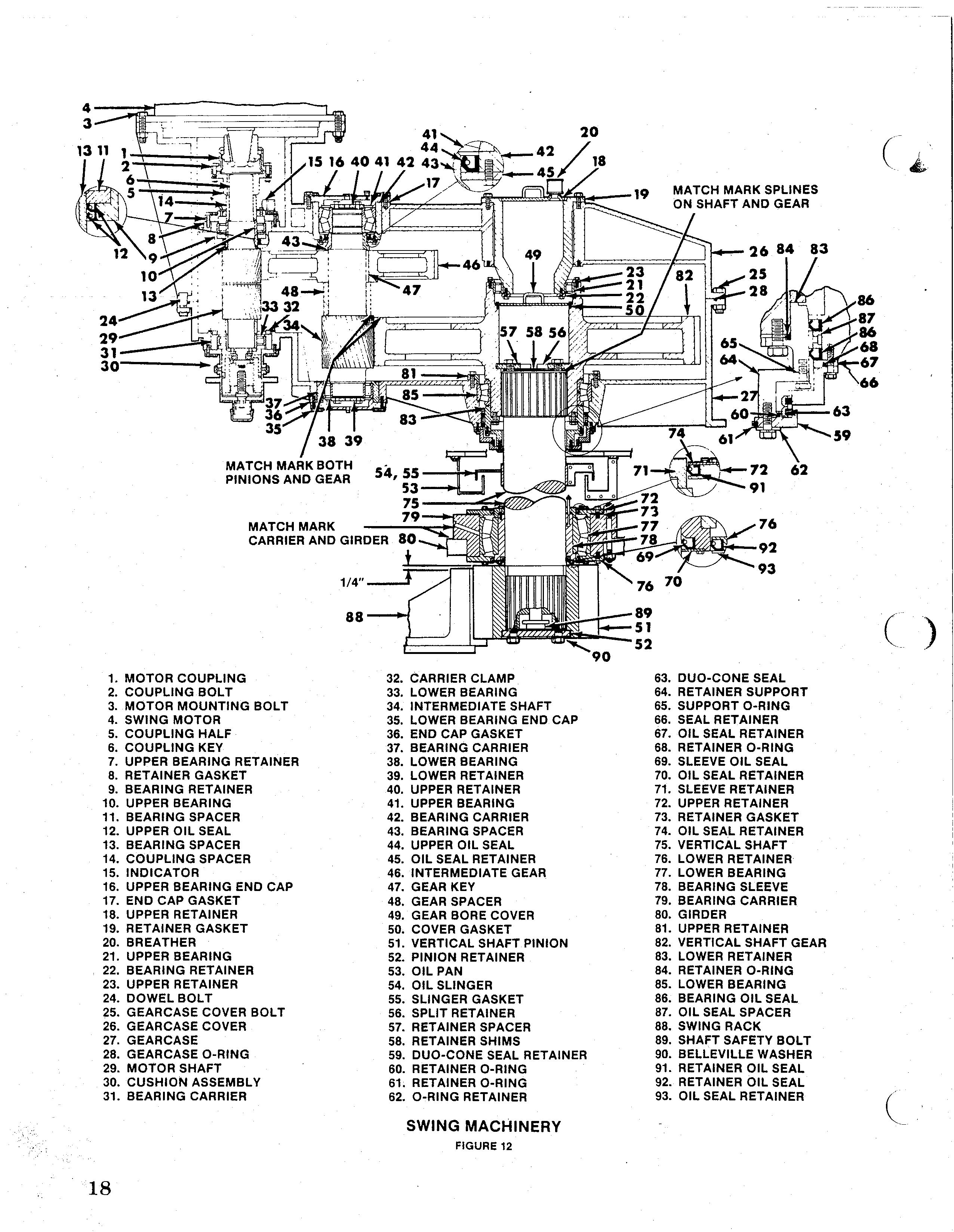
1. MOTOR COUPLING 2. COUPLING BOLT 3. MOTOR MOUNTING BOLT 4. SWING MOTOR 5. COUPLING HALF 6. COUPLING KEY 7. UPPER BEARING RETAINER 8. RETAINER GASKET 9. BEARING RETAINER 10. UPPER BEARING 11. BEARING SPACER 12. UPPER Oil SEAL 13. BEARING SPACER 14. COUPLING SPACER 15. INDICATOR 16. UPPER BEARING END CAP 17. END CAP GASKET 18. UPPER RETAINER 19. RETAINER GASKET 20. BREATHER 21. UPPER BEARING 22. BEARING RETAINER 23. UPPER RETAINER 24. DOWEL BOLT 25. GEAR CASE COVER BOLT 26. GEAR CASE COVER 27. GEARCASE 28. GEAR CASE O-RING 29. MOTOR SHAFT 30. CUSHION ASSEMBLY 31. BEARING CARRIER 32. CARRIER CLAMP 33. lOWER BEARING 34. INTERMEDIATE SHAFT 35. lOWER BEARING END CAP 36. END CAP GASKET 37. BEARING CARRIER 38. lOWER BEARING 39. lOWER RETAINER 40. UPPER RETAINER 41. UPPER BEARING 42. BEARING CARRIER 43. BEARING SPACER 44. UPPER Oil SEAL 45. Oil SEAL RETAINER 46. INTERMEDIATE GEAR 47. GEAR KEY 48. GEAR SPACER 49. GEAR BORE COVER 50. COVER GASKET 51. VERTICAL SHAFT PINION 52. PINION RETAINER 53. Oil PAN 54. Oil SLINGER 55. SLINGER GASKET 56. SPLIT RETAINER 57. RETAINER SPACER 58. RETAINER SHIMS 59. DUO-CONE SEAL RETAINER 60. RETAINER O-RING 61. RETAINER O-RING 62. O-RING RETAINER
SWING MACHINERY
66
63. DUO-CONE SEAL 64. RETAINER SUPPORT 65. SUPPORT O-RING 66. SEAL RETAINER 67. Oil SEAL RETAINER 68. RETAINER O-RING 69. SLEEVE Oil SEAL 70. Oil SEAL RETAINER 71. SLEEVE RETAINER 72. UPPER RETAINER 73. RETAINER GASKET 74. Oil SEAL RETAINER 75. VERTICAL SHAFT 76. lOWER RETAINER 77. lOWER BEARING 78. BEARING SLEEVE 79. BEARING CARRIER 80. GIRDER 81. UPPER RETAINER 82. VERTICAL SHAFT GEAR 83. lOWER RETAINER 84. RETAINER O-RING 85. lOWER BEARING 86. BEARING Oil SEAL 87. Oil SEAL SPACER 88. SWING RACK 89. SHAFT SAFETY BOLT 90. BEllEVillE WASHER 91. RETAINER Oil SEAL 92. RETAINER Oil SEAL 93. Oil SEAL RETAINER (
b. All bearings must be heated in an oil bath prior to installation. A CAUTION: Use suitable . protective equipment when handling the .heated items. c. The intermediate gear is interference fit to the shaft and the bore must be preheated prior to assembly. d. ·Use Permatex #98 or Silicone rubber between the gearcase and cover flanges when reassembling. e. Be sure all bolts are torqued, all electrical connections· made, all lube lines are installed, all gearcase filled to proper level, all monitor equipment installed and all guards replaced. Be sure all bearings are lubed.
SWING MACHINERY
There are four swing units on 1570W Walking Dragline (figure 11). The level of lubricant in the gearcase should be checked daily and lubricant added as required. All manually lubricated points should be lubricated daily. The daily inspection should also ihclude checking for leaking seals or gaskets. Weekly, check that the oil cup, which lubricates the vertical shaft upper seal, is fulL Periodically check the movement of the motor pinion shaft. Undue movement may indicate adjustment of the cushion may be required. Monthly, check the condition of the swing pinion retainer bolts. Periodically check the backlash between the verti- . cal shaft pinion and the swing rack. The backlash should be between .140 and .180 inch.
Repair Repair of the swing machinery (figure 12) will consist mainly of replacement of worn or damaged parts. Proceed as follows to disassemble the gear train. Repair procedure for the brakes is listed separately. Motor repair will be found in the Electrical Manual.
h CAUTION: The following procedure is .. for complete disassembly of a swing unit. If only portions of the unit are to be additional precautions must be taken to insure against unwanted movement of parts not being disassembled. 1. Move the machine to a safe area with sufficient room to perform the maintenance.
2. Set the walking shoes and bucket on the ground. Set all brakes. Turn the controls to the "off' position and lock and tag them. h CAUTION: At least one swing brake .. should be set at all times to prevent unwanted movement of the machine.
3. Have an electrician disconnect and tag the motor electrical connections. Also have him remove any monitoring equipment. 4. Remove all lube lines and drain the gearcase. 5. Remove inspection covers to expose the motor coupling and remove the coupling bolts. Remove the motor mounting bolts and lift the motor and brake from the gearcase. 6. With a puller, remove the coupling half from the motor pinion shaft. Remove the coupling key. .
NOTE: Pressure required to remove coupling half will be in excess of 45 tons, therefore, in addition to the puller, the coupling will have to be heated with a torch. When using the torch, be sure all safety precautions are followed. 7. Remove the double row of bolts securing the motor shaft upper bearing retainer to the gearcase cover and bearing carrier. Remove the retainer from the shaft. Remove the oil seal retainer and oil seal from the bearing retainer.
Remove the bearing retainer gasket. Remove the coupling spacer from the shaft. 8. Screw two eyebolts into the bearing carrier 1800 Use the eyebolts to lift the bearing carrier from the shaft. Remove the. bearing cage, spacer and oil seals from the carrier. The bearing inner race and lower spacer will re- . main on the shaft. These items should be removed only if the bearing is to be replaced as the inner race will most likely be damaged during removal.' 9. If the swing unit is equipped with a swing, ,. recorder (figure 13), remove the recorder. Re-' I, move the fork drive from the recorder drive shaft, then remove the recorder and base. If the unit is equipped with a position sensor (figure 14) unbolt and remove the bracket and sensor as an assembly. 10. Remove both rows of bolts securing the intermediate shaft upper bearing end caps to the gearcase cover and bearing carriers. Remove the bearing end caps and gaskets.