1 minute read
BEARING CAP GIB KEY


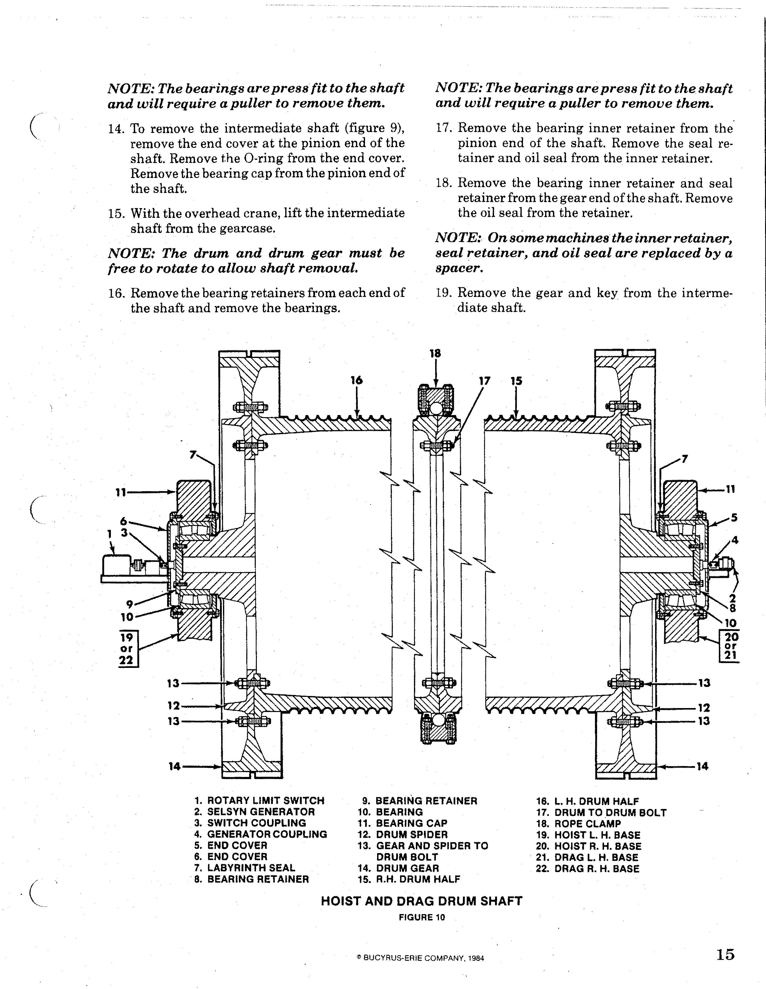
NOTE: The bearings are press/it to the shaft and will require a puller to remove them. 14. To remove the intermediate shaft (figure 9), remove the end cover at the pinion end of the shaft. Remove t.he O-ring from the end cover.
15. With the overhead crane, lift the intermediate shaft from the gearcase. NOTE: The drum and drum gear must be free to rotate to allow shaft removal. 16. Remove the bearing retainers from each end of the shaft and remove the bearings. NOTE: The bearings are press fit to the. shaft and will require a puller to remove them. 17. Remove the bearing inner retainer from the' pinion end of the shaft. Remove the seal retainer and oil seal from the inner retainer.
18. Remove the bearing inner retainer and seal retainer from the gear end of the shaft. Remove the oil seal from the retainer.
NOTE: On some machines the inner retainer, seal retainer, and oil seal are replaced by a spacer. 19. Remove the gear and key from the intermediate shaft.
1. ROTARY LIMIT SWITCH 9. BEARING RETAINER 16. L. H. DRUM HALF 2. SELSYN GENERATOR 10. BEARING 3. SWITCH COUPLING 11. BEARING CAP 4. GENERATOR COUPLING 12. DRUM SPIDER 5. END COVER 6. END COVER 7. LABYRINTH SEAL 8. BEARING RETAINER 13. GEAR AND SPIDER TO DRUM BOLT 14. DRUM GEAR 15. R.H. DRUM HALF 17. DRUM TO .DRUM BOLT 18. ROPE CLAMP 19. HOIST L. H. BASE 20. HOIST R. H. BASE 21. DRAG L. H. BASE 22. DRAG R. H. BASE
HOIST AND DRAG DRUM SHAFT