1 minute read
GEARCASE OIL GAUGE


Repair Repair of the hoist or drag machinery will consist of replacement of worn or damaged parts. Proceed as follows to disassemble the hoist or drag machinery gear train. Repair procedures for the brakes are listed separately. Motor repair will be found in the Electrical Manual. h. CAUTION: The following procedure is .. for complete disassembly of the hoist or drag machinery. If only portions of the unit are to be removed, additional precautions must be taken to insure against unwanted movement of parts not being disassembled.
L Move the machine to a safe area with sufficient room to perform the maintenance. 2. Set the walking shoes and bucket on the ground. Set all brakes and turn the controls to the "off' position and lock and tag them.
Rem()ve the hoist and drag ropes as described inthe topics HOIST ROPE REPLACEMENT and DRAG ROPE REPLACEMENT. 3. Remove the brakes from the motors using the procedure as outlined in the topic BRAKES.
4. Remove the coupling guard and separate the coupling.
5. Have an electrician disconnect the motor from the power source and tape and tag the cable ends.
6. The units of the hoist and drag machinery will be handled with the overhead crane. Unbolt the motors and remove them from the base.
7. Remove the lube lines to the first reduction gearcase,· second reduction guards and drum pedestal. Remove the second reduction guards.
NOTE: Prior to removing the second reduction guards, it may be necessary to remove miscellaneous items such as dirt shields, slack rope detectors, etc.
3
10
"J.t---+-- 4
__ ;--_ 11
13 ---Ho-t'J
2---il
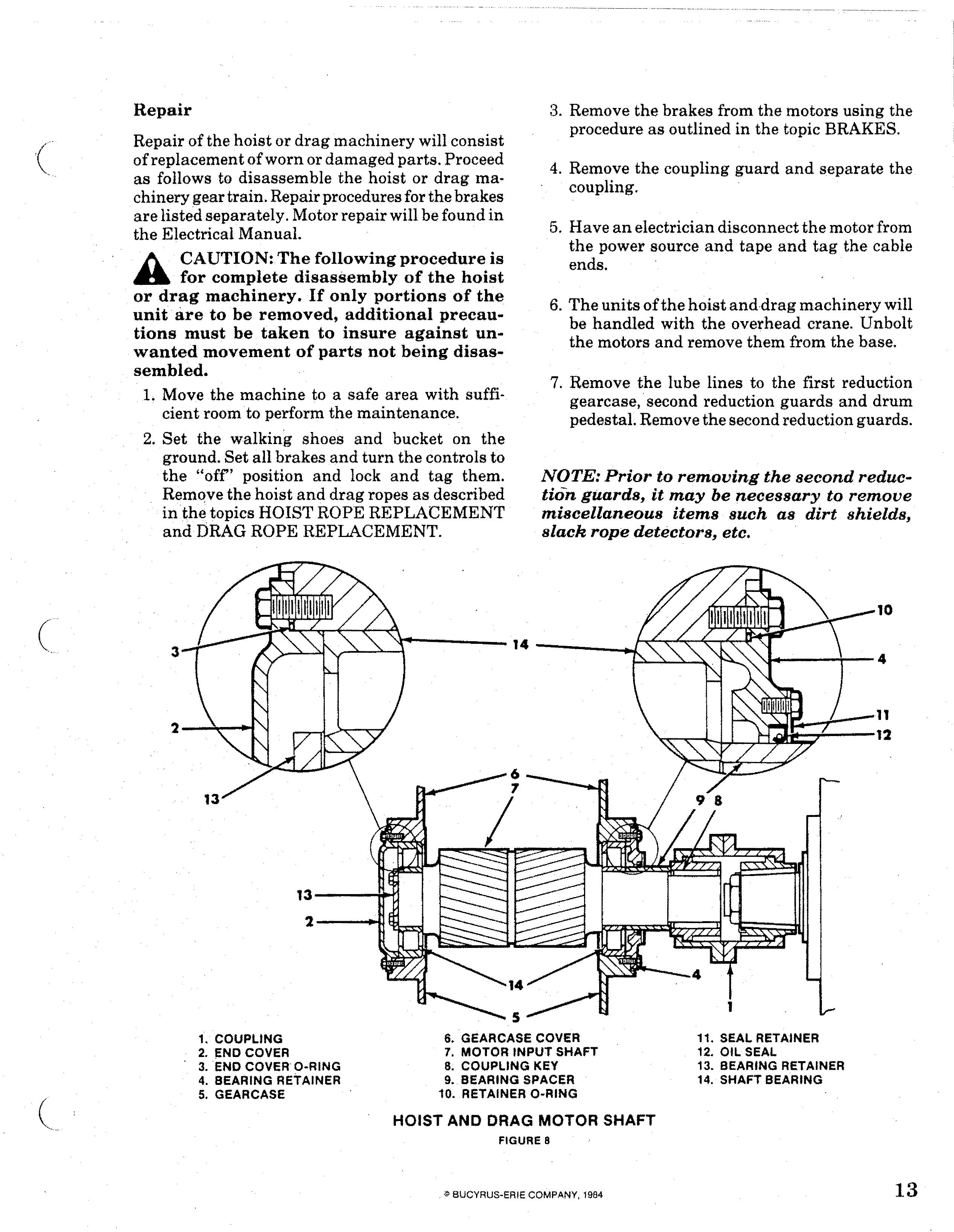
1. COUPLING 2. END COVER 3. END COVER O-RING 4. BEARING RETAINER 5. GEAR CASE 6. GEAR CASE COVER 7. MOTOR INPUT SHAFT 8. COUPLING KEY 9. BEARING SPACER 10. RETAINER O-RING
HOIST AND DRAG MOTOR SHAFT
11. SEAL RETAINER 12. OIL SEAL 13. BEARING RETAINER 14. SHAFT BEARING