BI005574
5. Remove and discard the piston O-ring.
6. Inspect the piston ring for scratches, gouges and other damage. Replace the piston ring if necessary.
lr~"''f+---10 INI_--8
9
7. Inspect the inner surface of the cylinder for any surface defects which can damage the piston ring or O-ring. The surface of the cylinder should be smooth and polished. If needed, the bore can be rebored to 0.015 inch oversize. If rebored, the cylinder must be polished to a 10 to 15 microunit surface finish. Replace the cylinder if it is badly damaged or worn. 8. Lightly lubricate a new O-ring and insert the O-ring in the groove of the piston. If removed, lubricate and install the piston ring. 9. Coat the bore of the cylinder lightly with oil and carefully lower the piston into the cylinder. Make sure the piston is not cocked in the cylinder.
19 --",,-,/
10. Install the piston and cylinder assembly on the brake. Secure the cylinder with the stud nuts, making sure all nuts are snug and equally torqued to distribute the load evenly to each stud. lS
11. Reconnect the air line to the brake and test the brake function. 17
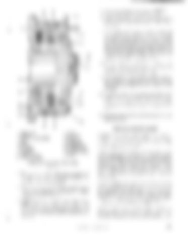
1. 2. 3. 4. 5. 6. 7. 8. 9. 10.
16
PUSH STUD SPRING COLLAR W/SET SCREW SEAL RING PISTON CYLINDER ADAPTER ADAPTER SEAL ADAPTER SCREW
DRAGLINE BUCKET 11. 12. 13. 14. 15. 16. 17. 18. 19.
NUT WASHER STUD STUD PIN DRIVE RING OUTER PLATE CENTER PLATE DISC ASSEMBLY HUB
FAIRLEAD RESTRICTION BRAKE FIGURE 78
2. Remove the cylinder stud nuts securing the cylinder to the brake drive ring and remove the cylinder and piston as a unit. 3. Clean the inboard side of the cylinder bore to remove any loose dirt or contaminants. Lightly lubricate the cylinder bore. 4. Insert bolts in the tapped puller holes of the piston, and lift the piston from the cylinder. Do not attempt to use air pressure to remove the piston from the cylinder as the cylinder can be damaged.
©
Should components break, repair all materials used in fabricating the bucket by pr.eheating, torching and welding. Refer to Appendix for repair welding information. Inspect tooth tips frequently for abrasion, cracking, or shearing of any nature. To replace a tooth, remove the wedge connection between the tooth tip and its horn (base). Cap the horn with a new tooth tip and apply a new wedge for the assembly. Then trim the protruding upper and lower portions of the wedge flush with the top and bottom surfaces of the tooth tip. Carefully inspect the tooth horns (bases) each time tooth points are replaced. Templates can be ordered for checking sides and slopes of the tooth horn. Rebuild worn tooth horns to prevent tooth point breakage or subsequent tooth horn fracture. Refer to Appendix for tooth horn rebuilding data. Optional reinforcing shrouds (figure 79) may be provided on the corners of the bucket and on the bottom ofthe bucket between adjacent shoe horns.
BUCYRUS-ERIE COMPANY, 1983
79


