
7 minute read
Dragline Bucket


19 --",,-,/ 0
INI_--8
9
lS
17
1. PUSH STUD 2. SPRING 3. COLLAR W/SET SCREW 4. SEAL 5. RING 6. PISTON 7. CYLINDER 8. ADAPTER 9. ADAPTER SEAL 10. ADAPTER SCREW 16
11. NUT 12. WASHER 13. STUD 14. STUD PIN 15. DRIVE RING 16. OUTER PLATE 17. CENTER PLATE 18. DISC ASSEMBLY 19. HUB
FAIRLEAD RESTRICTION BRAKE
FIGURE 78
2. Remove the cylinder stud nuts securing the cylinder to the brake drive ring and remove the cylinder and piston as a unit.
3. Clean the inboard side of the cylinder bore to remove anyloose dirtor contaminants. Lightly lubricate the cylinder bore.
4. Insert bolts in the tapped puller holes of the piston, and lift the piston from the cylinder. Do not attempt to use air pressure to remove the piston from the cylinder as the cylinder can be damaged. 6. Inspect the piston ring for scratches, gouges and other damage. Replace the piston ring if necessary.
7. Inspect the inner surface of the cylinder for any surface defects which can damage the piston ring or O-ring. The surface of the cylinder should be smooth and polished. If needed, the bore can be rebored to 0.015 inch oversize. If rebored, the cylinder must bepolished to a 10to 15 microunit surface finish. Replace the cylinder ifit is badly damaged or worn.
8. Lightly lubricate a new O-ring and insert the
O-ring in the groove of the piston. Ifremoved, lubricate and install the piston ring.
9. Coat the bore of the cylinder lightly with oil and carefully lower the piston into the cylinder.
Make sure the piston is not cocked in the cylinder.
10. Install the piston and cylinderassembly on the brake. Secure the cylinder with the stud nuts, making sure all nuts are snug and equally torqued to distribute the load evenly to each stud.
11. Reconnect the air line to the brake and test the brake function.
DRAGLINE BUCKET
Should components break, repair all materials used in fabricating the bucket by pr.eheating, torching and welding. Refer to Appendix for repair welding information.
Inspect tooth tips frequently for abrasion, cracking, or shearing of any nature. To replace a tooth, remove the wedge connection between the tooth tip and its horn (base). Cap the horn with a new tooth tip and apply a new wedge for the assembly. Then trim the protruding upper and lowerportions ofthe wedge flush with the top and bottom surfaces of the tooth tip. Carefullyinspect thetooth horns (bases) each time tooth points are replaced. Templates can be ordered for checking sides and slopes of the tooth horn. Rebuild worn tooth horns to prevent tooth point breakage or subsequent tooth horn fracture. Refer to Appendix for tooth horn rebuilding data.
Optional reinforcing shrouds (figure 79) may be provided on the corners of the bucket and on the bottom ofthe bucket between adjacent shoe horns.
CENTER SHROUDS
FIGURE 79 CENTER SHROUD LIP
If wear or breakage necessitates shroud replacement, refer to Appendix for welding information.
The side and bottom plates provide critical reinforcement for the bucket. Consequently, they should be checked regularly for fatigue and component failure. When wear spots develop in the side and bottom plates, the metal contour can be restored by building up the affected area. Refer to Appendix for welding information.
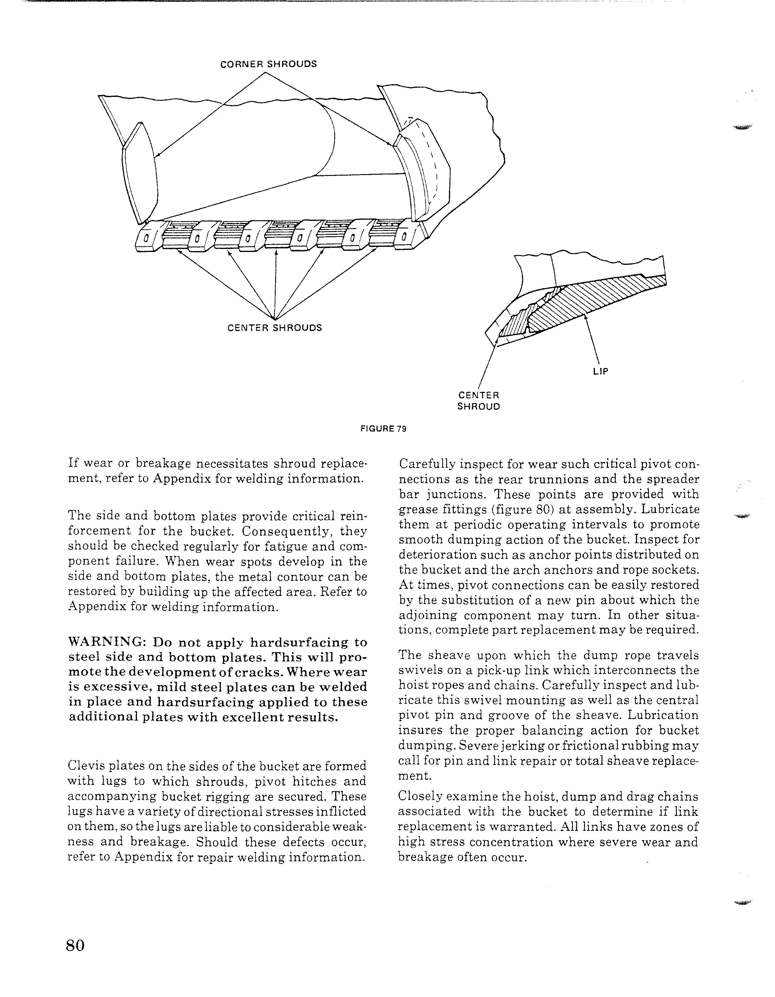
WARNING: Do not apply hardsurfacing to steel side and bottom plates. This will promote the development ofcracks. Where wear is excessive, mild steel plates can be welded in place and hardsurfacing applied to these additional plates with excellent results.
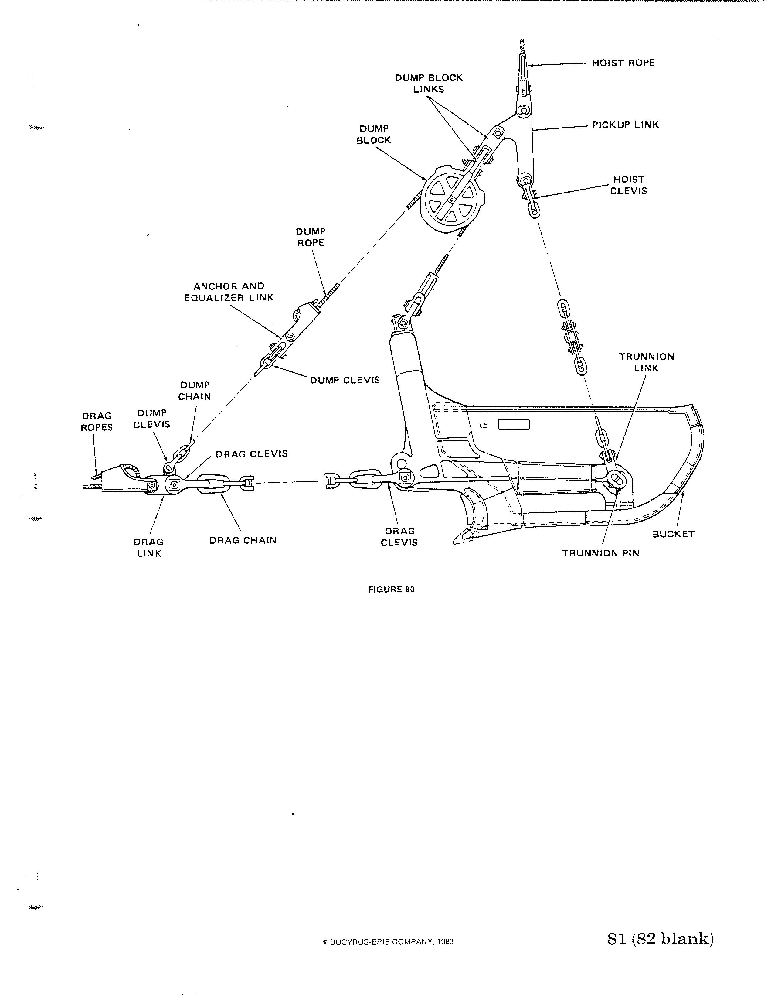
Clevis plates on the sides of the bucket are formed with lugs to which shrouds, pivot hitches and accompanying bucket rigging are secured. These lugs have a variety ofdirectional stresses inflicted on them, so the lugs areliable to considerable weakness and breakage. Should these defects occur, refer to Appendix for repair welding information. Carefully inspect for wear such critical pivot connections as the rear trunnions and the spreader bar junctions. These points are provided with grease fittings (figure 80) at assembly. Lubricate them at periodic operating intervals to promote smooth dumping action of the bucket. Inspect for deterioration such as anchor points distributed on the bucket and the arch anchors and rope sockets. At times, pivot connections can be easily restored by the substitution of a new pin about which the adjoining component may turn. In other situations, complete part replacement may be required.
The sheave upon which the dump rope travels swivels on a pick-up link which interconnects the hoist ropes and chains. Carefully inspect and lubricate this swivel mounting as well as the central pivot pin and groove of the sheave. Lubrication insures the proper balancing action for bucket dumping. Severejerking orfrictional rubbing may call for pin and link repair or total sheave replacement. Closely examine the hoist, dump and drag chains associated with the bucket to determine if link replacement is warranted. All links have zones of high stress concentration where severe wear and breakage often occur.
DUMP BLOCK LINKS
DUMP BLOCK
ANCHOR AND EOUALIZER LINK DUMP ROPE \ /
DRAG ROPES DUMP / CHAIN
DRAG LINK DRAG CHAIN DUMP CLEVIS
FIGURE 80 1----- PICKUP LINK
HOIST CLEVIS
SECTION 1- GENERAL MAINTENANCE
SAFETY
Whenever work is to be done on the compressed air system there are three important safety rules to follow:
1. Thrn the air compressor switch on the operator's console to the "off' position and attach a warning sign to the switch.
2. Open the auxiliary power circuit breaker and attach a warning sign to the breaker.
3. Drain the compressed air from the air tank and air lines.
GENERAL
The air system (figure 81) on the 1370W Walking Dragline consists of two air compressors, driven by electric motors, which supplies air to an air tank. The air is then routed from the air tank to the brakes, boom pressurization system, lubrication system, propel transfer switch, and miscellaneous optional components. The system is protected and monitored for failure by safety valves, check valves and pressure switches. The compressed air as it passes through the air lines is filtered, lubricated and regulated. In addition electro-mechanical valves are located in the system to control the air to the various components.
MAINTENANCE OF AIR SYSTEM
The maintenance of the air system consists of periodic checks (each shift, daily, weekly, etc.) to assure the system is working correctly. It also requires minor adjustments and repairs as problems are found. The actual repair procedures will be found in Section 2 of this chapter titled COMPONENT MAINTENANCE, in Chapter 1 for maintenance ofthe various brakes and in the case of some items separate Vendor manuals.
AIR COMPRESSOR
The following checks are for the standard compressor supplied with the Model 1370W Dragline which is a Kellogg-American air compressor. If the machine is equipped with another compressor refer to that Manufacturer's manual.
1. Daily check for unusual noise, failure to compress, overheating, vibration or belt slippage.
Adjust the belt if required. If any of the other symptoms are found refer to the air compressor troubleshooting in Section 2. 2. Once a week examine the intake filter element and clean or replace if necessary.
3. Every shift check the oil level and add oil if required. Add only enough oil to bringthe level up to, but not above, the mark on the oil gauge.
Everythree months changethe oil. Refer to the oil specification in Section 2.
lVOTE: Continuously operating compressors in daily use and units subject to heavy duty should have oil changed more often.
4. Keep the compressor clean for efficient operation as well as appearance.
5. Once a month check and tighten all bolts, as required. Section 2 contains a tabulation of specific bolts and their required torque values.
6. Ifthe compressor has been briefly shutoffand air leaks from the centrifugal unloaded filter opening the compressor to air tank line check valve is leaking. Repair or replace the check valve as necessary.
NOTE: Be sure the rotation of the compressor is correct or the weight retainer assembly in the centrifugal unloader will quickly work loose.
AIRLINES
Dailv check the air lines for loose or damaged hose and piping. Also check for leaking of air at the fittings. Tighten loose fittings and replace damaged or worn lines.


