4 minute read
Straight Through Type Fairlead


8. Position the reels of new drag rope in front of the machine. Attach the deck winch lines to the new drag ropes. Remove the staples securing the new rope to the reels.
i\. CAUTION: When removingthe staples, .. be sure to stand to the side as the rope will snap downward when the staples are removed.
9. With the right deck winch pull the right drag rope onto the machine and into the rope clamp sockets on the drum. Secure the rope to the drum with the rope clamps and disconnect the winch line from the drag rope.
10. Rotate the drag drum 180 0 to put the left drum drag rope clamp sockets in position for installing the rope.
11. With the deck winch pull the left drag rope onto the machine and into the rope clamp sockets on the drum. Secure the rope to the drum with the rope clamps and disconnect the winch line from the drag rope.
12. Take up on the drag machinery to reel the drag rope onto the drums. Make sure the ropes seat properly in the drum rope grooves. Stop the drag machinery when the ropes are off the reels. Disconnect the ropes from the reels and remove the reels from the area.
13. Connect the drag ropes to the bucket drag sockets.
FAIRLEAD
There are two types offairlead which are used on the model 1370W Walking Dragline-the straight through type and the over and under type.
The mountings and frames should be checked weekly for cracking or other signs of structural damage. The condition of the limiting ropes or chains should also be checked. Check all sheaves for wear or damage. On the straight through type fairlead, check the buffer cylinder for proper operation. Also check the buffer cylinder support.
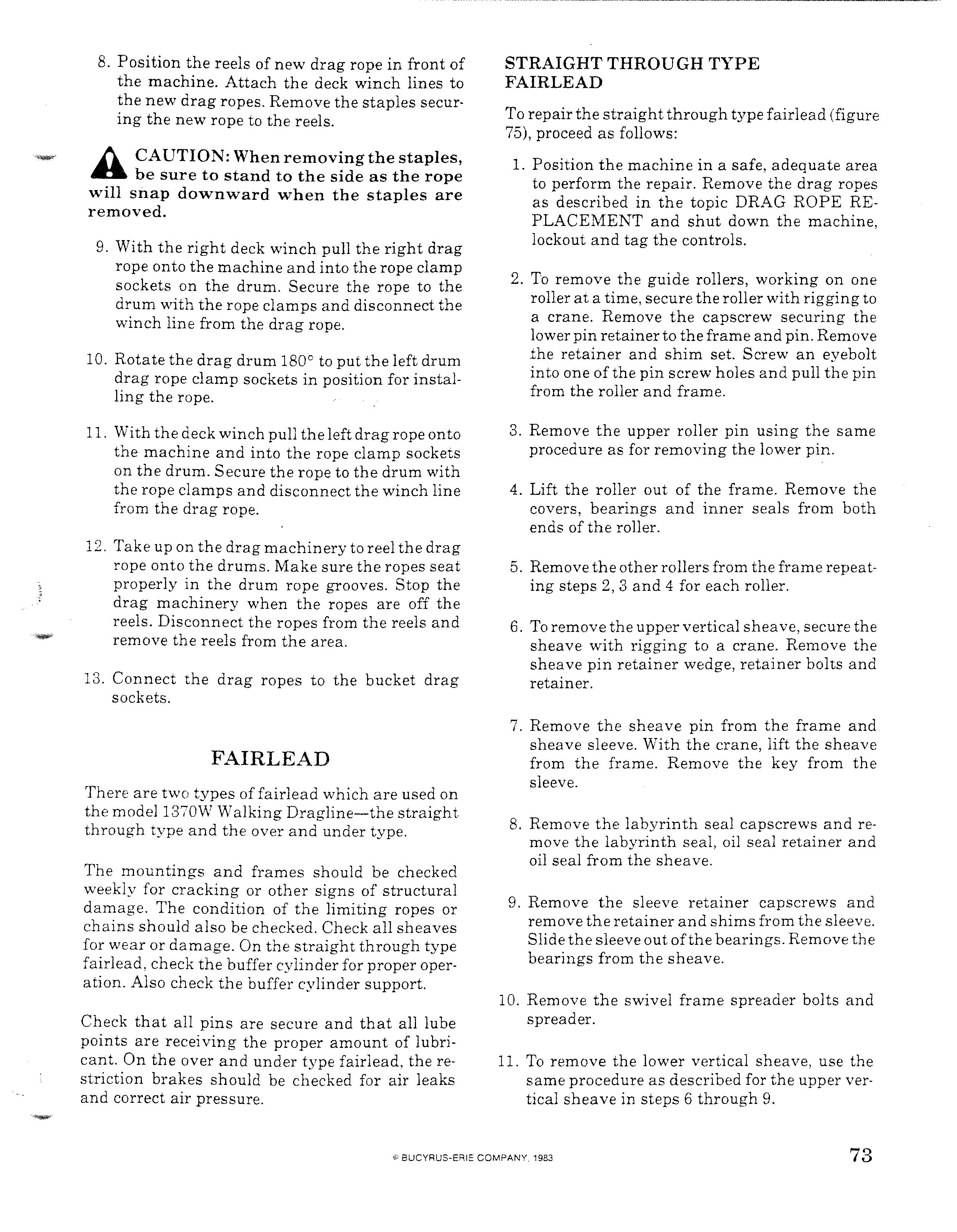
Check that all pins are secure and that all lube points are receiving the proper amount of lubricant. On the over and under type fairlead, the restriction brakes should be checked for air leaks and correct air pressure. To repairthe straightthrough type fairlead (figure 75), proceed as follows:
1. Position the machine in a safe, adequate area to perform the repair. Remove the drag ropes as described in the topic DRAG ROPE RE-
PLACEMENT and shut down the machine, lockout and tag the controls.
2. To remove the guide rollers, working on one roller at a time, secure the roller with rigging to a crane. Remove the capscrew securing the lower pin retainerto theframe and pin. Remove the retainer and shim set. Screw an eyebolt into one of the pin screw holes and pull the pin from the roller and frame.
3. Remove the upper roller pin using the same procedure as for removing the lower pin.
4. Lift the roller out of the frame. Remove the covers, bearings and inner seals from both ends of the roller.
5. Remove the otherrollers from the frame repeating steps 2, 3 and 4 for each roller.
6. To remove the upper vertical sheave, secure the sheave with rigging to a crane. Remove the sheave pin retainer wedge, retainer bolts and retainer.
7. Remove the sheave pin from the frame and sheave sleeve. With the crane, lift the sheave from the frame. Remove the key from the sleeve.
8. Remove the labyrinth seal capscrews and remove the labyrinth seal, oil seal retainer and oil seal from the sheave.
9. Remove the sleeve retainer capscrews and remove the retainer and shims from the sleeve.
Slidethe sleeve out ofthe bearings. Remove the bearings from the sheave.
10. Remove the swivel frame spreader bolts and spreader.
11. To remove the lower vertical sheave, use the same procedure as described for the upper vertical sheave in steps 6 through 9.
3--"""
1. GUIDE ROLLER 2. PIN RETAINER 3. ROLLER PIN 4. COVER 5. BEARING 6. INNER SEAL 7. UPPER VERT. SHEAVE 8. SHEAVE PIN 9. PIN RETAINER 10. RETAINER WEDGE 11. SLEEVE KEY 12. SLEEVE RETAINER 13. SLEEVE 14. SHIM SET 15. LABYRINTH SEAL 16. SEAL RETAINER 17. OIL SEAL 18. SPREADER 19. SWIVEL FRAME-R.H. 20. SWIVEL FRAME-L.H. 11

....,.-r-/ ...Ir 10
13
9
21
1 \
29 7
30 32
26-_-"-,,
27---;..;._
22
21. LOWER VERT. SHEAVE 22. SHEAVE PIN 23. PIN RETAINER 24. RETAINER WEDGE 25. SLEEVE KEY 26. SLEEVE RETAINER 27. SHIM SET 28. SLEEVE 29. BEARING 30. BEARING 31. SEAL RETAINER 32. LABYRINTH SEAL 33. OIL SEAL 34. SHIM SET 35. DIRT SHIELD-OUTER 36. SHEAVE PIN-OUTER 37. PIN RETAINER 38. LOCK BAR 39. LOCK NUT 40. SLEEVE-OUTER 41. BEARING 42. LABYRINTH SEAL 43. HORIZ. SHEAVE 44. DIRT SHIELD-CENTER 45. SHEAVE PIN-CENTER 46. PIN RETAINER 47. FAIRLEAD FRAME 48. DIRT TROUGHS
STRAIGHT THROUGH TYPE FAIRLEAD
FIGURE 75
3128
21 31
49. UPPER PIN 50. PIN RETAINER 51. DIRT SHIELD 52. SWIVEL FRAME BUSHING 53. LOWER PIN 54. SHIM SET 55. PIN RETAINER 56. RETAINER BOLT 57. THRUST WASHER 58. CHOCKS 59. DIRT SHIELD 60. GASKET 61. THRUST PLATE & WASHERS 62. UPPER BUSHING 63. LOWER BUSHING 64. SLEEVE-CENTER 65. BUFFER CYLINDER 66. BUFFER CYLINDER SUPPORT 67. CYLINDER OIL RESERVOIR 68. LIMITING ROPE


