3 minute read
Over and Under Type Fairlead , " '"


1
'23 13
1
6
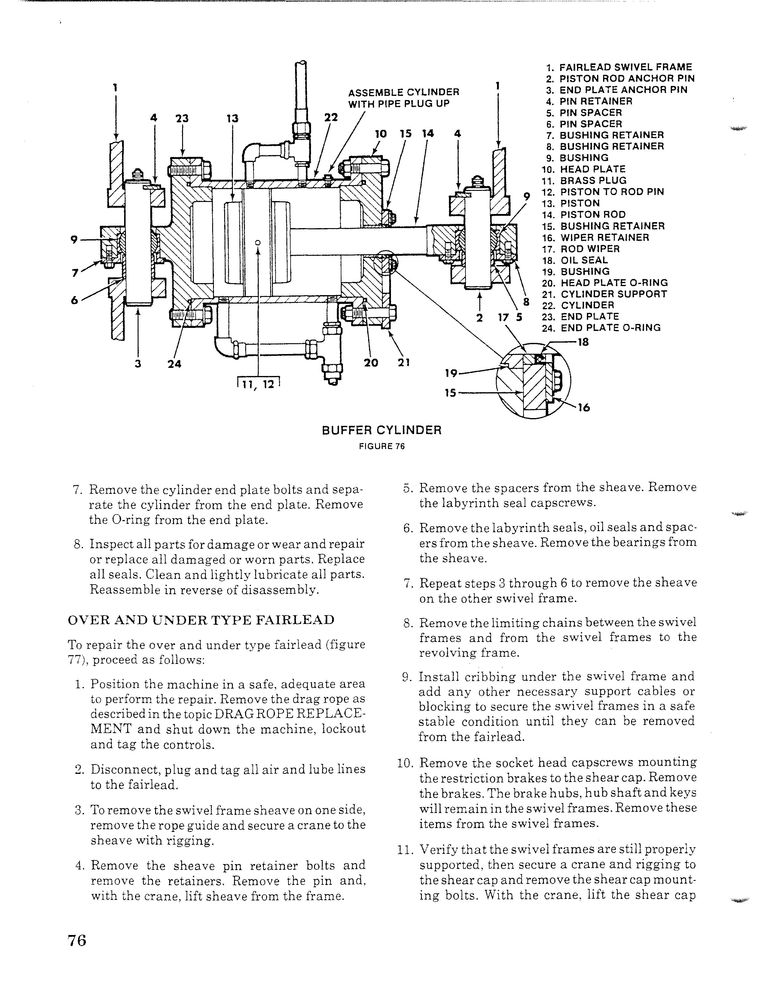
1. FAIRLEAD SWIVEL FRAME 2. PISTON ROD ANCHOR PIN 3. END PLATE ANCHOR PIN 4. PIN RETAINER 5. PIN SPACER 6. PIN SPACER 7. BUSHING RETAINER 8. BUSHING RETAINER 9. BUSHING 10. HEAD PLATE 11. BRASS PLUG 12. PISTON TO ROD PIN 13. PISTON 14. PISTON ROD 15. BUSHING RETAINER 16. WIPER RETAINER 17. ROD WIPER 18. OIL SEAL 19. BUSHING 20. HEAD PLATE O-RING 21. CYLINDER SUPPORT 22. CYLINDER 23. END PLATE 24. END PLATE O-RING '--,---18
BUFFER CYLINDER
FIGURE 76 16
7. Remove the cylinder end plate bolts and separate the cylinder from the end plate. Remove the O-ring from the end plate. 8. Inspect all parts for damage orwear and repair or replace all damaged or worn parts. Replace all seals. Clean and lightly lubricate all parts.
Reassemble in reverse of disassembly.
OVER AND UNDER TYPE FAIRLEAD
To repair the over and under type fairlead (figure 77), proceed as follows: 1. Position the machine in a safe, adequate area to perform the repair. Remove the drag rope as described in the topic DRAGROPE REPLACE-
MENT and shut down the machine, lockout and tag the controls.
2. Disconnect, plug and tag all air and lube lines to the fairlead.
3. To remove the swivel frame sheave on one side, remove the rope guide and secure a crane to the sheave with rigging.
4. Remove the sheave pin retainer bolts and remove the retainers. Remove the pin and, with the crane, lift sheave from the frame. 5. Remove the spacers from the sheave. Remove the labyrinth seal capscrews.
6. Remove the labyrinth seals, oil seals and spacers from the sheave. Removethe bearingsfrom the sheave.
7. Repeat steps 3 through 6 to remove the sheave on the other swivel frame.
8. Remove the limiting chains between the swivel frames and from the swivel frames to the revolving frame. 9. Install cribbing under the swivel frame and add any other necessary support cables or blocking to secure the swivel frames in a safe stable condition until they can be removed from the fairlead.
10. Remove the socket head capscrews mounting the restriction brakes to the shear cap. Remove the brakes. The brake hubs, hub shaft and keys will remain in the swivel frames. Remove these items from the swivel frames.
11. Verify that the swivel frames are still properly supported, then secure a crane and rigging to the shear cap andremove the shearcap mounting bolts. With the crane, lift the shear cap
29 19
30
21 j
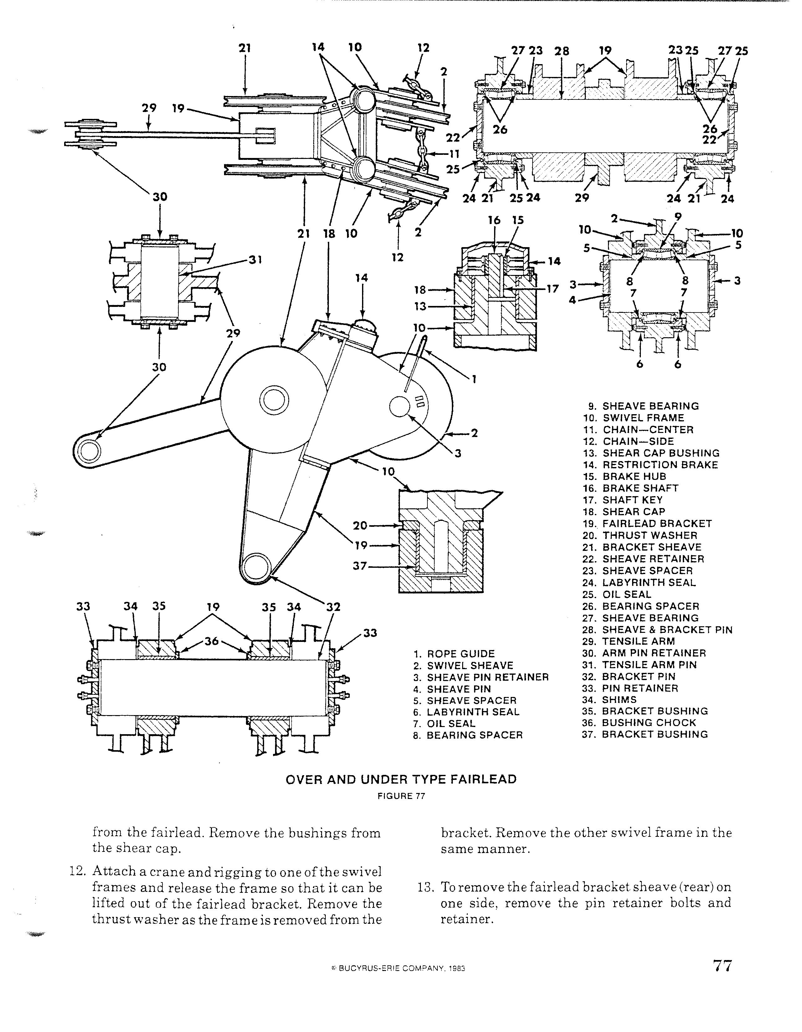
1. ROPE GUIDE 2. SWIVEL SHEAVE 3. SHEAVE PIN RETAINER 4. SHEAVE PIN 5. SHEAVE SPACER 6. LABYRINTH SEAL 7. OIL SEAL 8. BEARING SPACER
9. SHEAVE BEARING 10. SWIVEL FRAME 11. CHAIN-CENTER 12. CHAIN-SIDE 13. SHEAR CAP BUSHING 14. RESTRICTION BRAKE 15. BRAKE HUB 16. BRAKE SHAFT 17. SHAFT KEY 18. SHEAR CAP 19. FAIRLEAD BRACKET 20. THRUST WASHER 21. BRACKET SHEAVE 22. SHEAVE RETAINER 23. SHEAVE SPACER 24. LABYRINTH SEAL 25. OIL SEAL 26. BEARING SPACER 27. SHEAVE BEARING 28. SHEAVE & BRACKET PIN 29. TENSILE ARM 30. ARM PIN RETAINER 31. TENSILE ARM PIN 32. BRACKET PIN 33. PIN RETAINER 34. SHIMS 35. BRACKET BUSHING 36. BUSHING CHOCK 37. BRACKET BUSHING
OVER AND UNDER TYPE FAIRLEAD
FIGURE 77
from the fairlead. Remove the bushings from the shear cap. 12. Attach a crane and rigging to one ofthe swivel frames and release the frame so that it can be lifted out of the fairlead bracket. Remove the thrust washer as the frame is removed from the bracket. Remove the other swivel frame in the same manner.
13. To remove the fairlead bracket sheave (rear) on one side, remove the pin retainer bolts and retainer.


