BI005574 1. 2. 3. 4. 5. 6. 7. 8. 9. 10. 11. 12. 13. 14. 15. 16. 17. 18. 19. 20. 21. 22. 23. 24.
1 '23
13
1 6
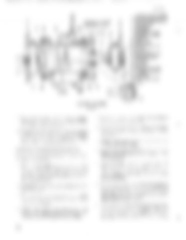
FAIRLEAD SWIVEL FRAME PISTON ROD ANCHOR PIN END PLATE ANCHOR PIN PIN RETAINER PIN SPACER PIN SPACER BUSHING RETAINER BUSHING RETAINER BUSHING HEAD PLATE BRASS PLUG PISTON TO ROD PIN PISTON PISTON ROD BUSHING RETAINER WIPER RETAINER ROD WIPER OIL SEAL BUSHING HEAD PLATE O-RING CYLINDER SUPPORT CYLINDER END PLATE END PLATE O-RING
'--,---18
16
BUFFER CYLINDER FIGURE 76
7. Remove the cylinder end plate bolts and separate the cylinder from the end plate. Remove the O-ring from the end plate. 8. Inspect all parts for damage or wear and repair or replace all damaged or worn parts. Replace all seals. Clean and lightly lubricate all parts. Reassemble in reverse of disassembly.
OVER AND UNDER TYPE FAIRLEAD To repair the over and under type fairlead (figure 77), proceed as follows: 1. Position the machine in a safe, adequate area
to perform the repair. Remove the drag rope as described in the topic DRAG ROPE REPLACEMENT and shut down the machine, lockout and tag the controls. 2. Disconnect, plug and tag all air and lube lines to the fairlead. 3. To remove the swivel frame sheave on one side, remove the rope guide and secure a crane to the sheave with rigging. 4. Remove the sheave pin retainer bolts and remove the retainers. Remove the pin and, with the crane, lift sheave from the frame.
76
5. Remove the spacers from the sheave. Remove the labyrinth seal capscrews. 6. Remove the labyrinth seals, oil seals and spacers from the shea ve. Remove the bearings from the sheave. 7. Repeat steps 3 through 6 to remove the shea ve on the other swivel frame. 8. Remove the limiting chains between the swivel frames and from the swivel frames to the revolving frame. 9. Install cribbing under the swivel frame and add any other necessary support cables or blocking to secure the swivel frames in a safe stable condition until they can be removed from the fairlead. 10. Remove the socket head capscrews mounting the restriction brakes to the shear cap. Remove the brakes. The brake hubs, hub shaft and keys will remain in the swi vel frames. Remove these items from the swivel frames. 11. Verify that the swivel frames are still properly supported, then secure a crane and rigging to the shear cap and remove the shear cap mounting bolts. With the crane, lift the shear cap


