BI000970
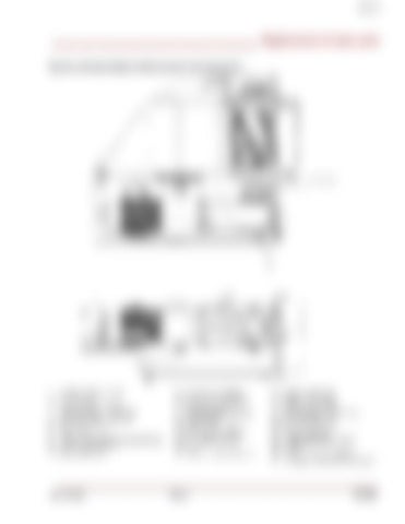
________________________________________ Replacement of wear parts Fig. 92, continued: Breaker shaft and power unit removal and
8, 7, 9, 10
31
1. 2. 3. 4. 5. 6. 7. 8. 9. 10.
Breaker shaft assembly Filler plate (2) Washer, lock 1-1/4 (24) Bolt, hex head 1-144X4 (20) Bolt, hex head 1-1/4X5 (4) Nut, hex 1-1/4 (24) Stub shaft Screw, socket head shoulder 1X3 (12) Washer, lock 3/4 (12) Nut, hex 3/4 (12)
11. 12. 13. 14. 15. 16. 17. 18. 19. 20.
Power unit assembly Bolt, hex head M30X80 Pivot lug weldment Mounting plate, pivot lug Reaction pin Washer, lock 1” (4) Bolt, hex head 1X2 (4) Pin, cotter 3/8X4 (2) Key Cylinder mount weldment
21. 22. 23. 24. 25. 26. 27. 28. 29. 30. 31.
Grease cylinder (3) Washer, flat 3/8 (6) Washer, lock 3/8 (6) Bolt, hex head 3/8X1-1/4 (6) Breaker retainer (2) Breaker retainer (2) Grease fitting (5) Underspeed sensor mount U-bolt Power unit guide assembly Low speed output shaft cover plate
______________________________________________________________ A6474X338 Rev 0 5.127


