1 minute read
Control features..............................................................5


foot cylinder locking pin
power fill ball valve
hydraulic oil level sight glass Controls and indicators - other locations
The following controls and indicators are located as described throughout the machine.
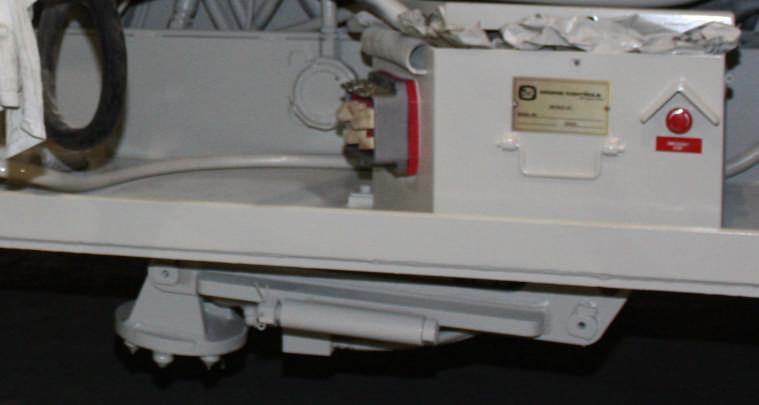
There is a mechanical locking pin on each foot cylinder (Fig. 21) that must be installed after the feeder is set in the dump position and the foot is planted. The locking pin will hold the cylinder in the extended position in the event that the foot cylinder counterbalance valve fails or is removed. Remove the pin before attempting to retract the cylinder.
Fig. 21: Foot cylinder mechanical locking pin
Locking pin storage tube
The power fill ball valve (Fig. 22) is located on the hydraulic oil tank on the left side of the machine and is used to open the hydraulic flow to the power fill pump. To operate the power fill, the ball valve must be opened, handle in line with the hydraulic line. Then the control handle on the primary valve bank (6th handle from the operator’s left is moved to the “POWER FILL” position (handle pushed forward). To deenergize the power fill pump, move the control lever to the centered position and turn ball valve handle to closed position.
CAUTION! The “POWER FILL/AUX VB” lever is the only lever on the primary valve bank that does not spring return to neutral when released. When the fill operation is complete, the lever must be manually returned to the neutral position. Failure to return the lever to neutral will result in the machine overheating.
The hydraulic oil level sight glass (Fig. 22) is located on the hydraulic oil tank on the left side of the machine. The oil level should not be allowed to drop below the bottom of the sight glass.