2 minute read
Every 3 months .............................................................5


Maintenance
tail shaft and slide tube bearings
Lubricate the feeder breaker tail shaft and slide tube bearings with Spec. 100-3 through the grease fittings located on right side of the machine at the primary operator’s station (Fig. 44). Pump grease into the four (4) fittings until new grease can be observed coming out of the tail shaft and bearings. To see the bearings, the tail shaft cover (Fig. 46) must be removed.
Fig. 46: Tailshaft and slide tube bearings
Grease fittings location (4)
Tail shaft bearing location
Slide tube bearing location Tail shaft bearing location
Slide tube bearing location
tailpiece pulley bearings
Grease the tailpiece bearings (Fig. 47) through the two grease fittings on the manifold located on the right side of the tailpiece (Fig. 47) with Spec. 100-3. Pump new grease into the fittings until old grease can be observed coming out of the bearing.
Fig. 47: Tailpiece bearing lubrication
Grease fitting manifold Tailpiece bearing (typical both sides)
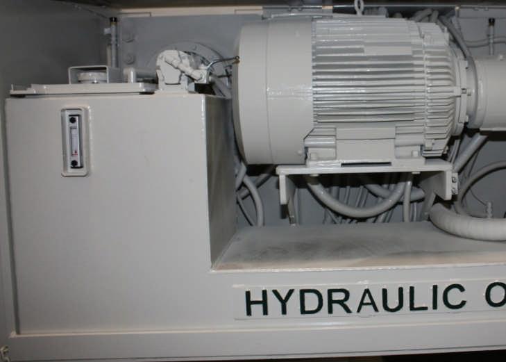
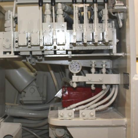
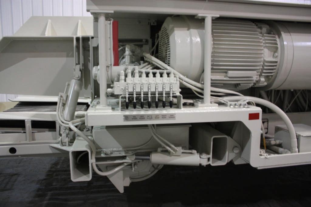
hydraulic oil tank Check the hydraulic oil level by looking at the sight glass located on the side of the oil tank (Fig. 48). The oil level should not be allowed to drop below the bottom of the sight glass. If the hydraulic oil level is low, add hydraulic oil (Spec. 100-1). To add oil via the power fill, reference the following procedure.
WARNING! The “TANK FILL/AUX VB” lever is the only lever on the valve bank that does not spring return to neutral when released. When not in use, the valve should be manually returned to the neutral position. Failure to do so could result in unexpected machine movement if the secondary valve bank is energized and a lever on the secondary valve bank is inadvertently moved or machine overheating if the power fill pump is left energized. Unexpected machine movement could result in serious injury to personnel or damage equipment.
To operate the power fill:
1. Clean suction hose attached to the hydraulic power fill motor, located on top of the oil tank.
Maintenance
Fig. 48: Hydraulic oil level check
2. Remove the suction hose plug and submerge the suction hose in the new oil supply.
3. Turn the handle of the ball valve to the open position. The handle should now be inline with the hydraulic hose to which it is attached.
4. Position the “TANK FILL/AUX VB” lever in the “TANK FILL” position. Oil from the valve bank will now drive the power fill motor and a suction force will be created in the suction line. Oil from the new oil supply will be drawn through the power fill motor to the hydraulic oil tank.
5. Once the tank is filled to the desired level, pull the power fill lever on the valve bank to the neutral (center) position.
6. Turn the ball valve handle 90° to close the ball valve.
7. Remove the suction hose from the new oil supply.
8. Clean and install hose plug into suction hose. Store the suction hose on top of the oil tank.
CAUTION! After oil filling operation is complete, manually return the “POWER FILL” lever to the centered, neutral, position or overheating of the machine may occur.
Sight glass Power fill ball valve