Cat 7MFBHM-48DD Feeder Breaker Operation & Maintenance Manual (1)

Page 109

BI000970

____________________________________________________ Maintenance pressure filter

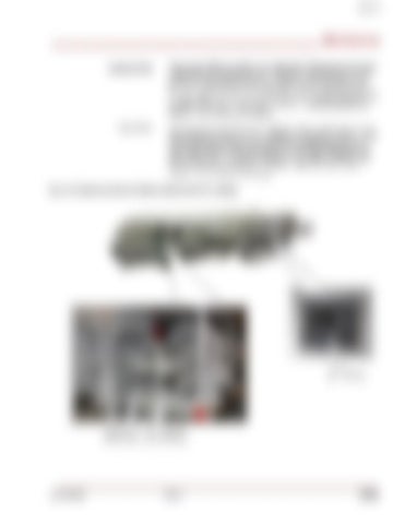
The pressure filter is located on the right side of the machine at the secondary operator’s station (Fig. 49). The filter is monitored by the PLC and when it reaches a preset limit, an alarm will be displayed on the PLC view panel, located on the right side of the machine on the starter enclosure (Fig. 49). The alarm will display on the ‘MAIN SCREEN” and will read “PRESSURE LINE DIRTY FILTER”. When the alarm is displayed, the filter should be changed.

return filter

The return filter is located on the right side of the machine at the secondary operator’s station (Fig. 49). The filter is monitored by the PLC and when it reaches a preset limit, an alarm will be displayed on the PLC view panel, located on the right side of the machine on the starter enclosure (Fig. 49). The alarm will display on the ‘MAIN SCREEN” and will read “RETURN LINE DIRTY FILTER”. When the alarm is displayed, the filter should be changed.

Fig. 49: Pressure and return filter locations and PLC display

PLC display

Return filter

Pressure filter

______________________________________________________________ A6474X338 Rev 0 5.65


Turn static files into dynamic content formats.

Create a flipbook

Articles inside

Lift cylinder ...................................................................5

2min
pages 189-190

Tailpiece tilt cylinder.....................................................5

1min
pages 191-192

Tilt cylinder ...................................................................5

1min
pages 187-188

Foot cylinder.................................................................5

2min
pages 185-186

Breaker bit removal ......................................................5

1min
page 178

Crawler track ...............................................................5

3min
pages 152-154

Tailpiece installation.....................................................5

4min
pages 179-182

Conveyor power unit.....................................................5

8min
pages 171-177

Tail shaft ......................................................................5

5min
pages 144-148

Crawler assembly ........................................................5

7min
pages 155-162

Dual relief valve manifold adjustment............................ 5

2min
pages 130-132

Flow control valve adjustment....................................... 5

1min
pages 135-136

Head shaft sprockets .................................................... 5

4min
pages 141-143

Hydrostatic pump charge pressure adjustment .............5

2min
pages 125-127

Secondary valve bank adjustment ................................ 5

1min
pages 133-134

Inspection of the feeder .....................................................5

1min
page 111

Every 6 months .............................................................5

1min
pages 109-110

Under speed sensor calibration .....................................5

1min
pages 121-122

Every 3 months .............................................................5

2min
pages 105-107

Every 2500 hours...........................................................5

1min
page 108

Head shaft .....................................................................5

1min
page 83

Major hydraulic components ....................................5

4min
pages 76-80

Breaker and breaker power unit assembly ....................5

5min
pages 85-86

Conveyor.............................................................................5

1min
page 64

Infrared pump motor controls..............................................5

2min
pages 65-66

Starter enclosure............................................................5

1min
pages 58-59

Control features..............................................................5

1min
page 60

Electrical system.................................................................5

2min
page 67

Shutdown procedure...........................................................5

1min
page 63

“TRAM ONLY” mode starting procedure.............................5

1min
page 62

Starter enclosure............................................................5

6min
pages 68-74
Issuu converts static files into: digital portfolios, online yearbooks, online catalogs, digital photo albums and more. Sign up and create your flipbook.
Cat 7MFBHM-48DD Feeder Breaker Operation & Maintenance Manual (1) by www.heydownloads.com - Issuu