10 minute read
BICS™ SYSTEM CONTROLLER (Cont’d)


Controller Test
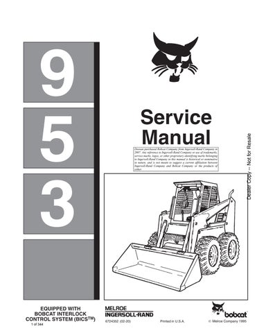
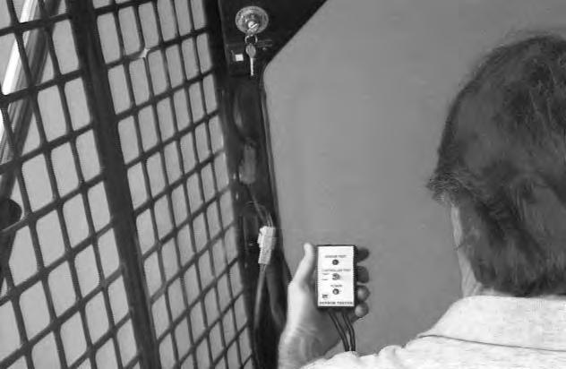
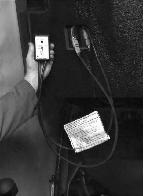
MEL1428 Sensor Tester is necessary for the following procedure:
Turn the key to the ON position. DO NOT START THE ENGINE
After completing the procedure for the Seat sensor test or the Seat Bar sensor test, do the Controller test. Refer to Page 8–3 for correct procedures to do the Seat Bar sensor test or the Seat sensor test.
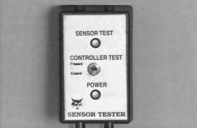
Move the toggle switch (Item 1) [A] on the sensor tester (Item 2) [A] to the Present position.
If the controller is working correctly, the Seat light (Item 1) [B] on the controller will illuminate when the tester is connected to the Seat sensor.


When the tester is connected to Seat Bar sensor, the Seat Bar light (Item 1) [C] will illuminate if the controller is working correctly.
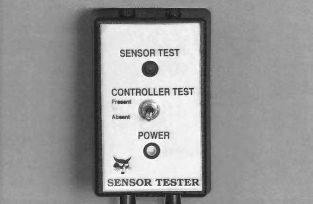
Move the toggle switch (Item 1) [D] on the sensor tester (Item 2) [D] to the Absent position.
The Seat light (Item 1) [B] or the Seat Bar light (Item 1) [C] should go off.
If the tests above fail, there is a problem with the BICS system controller or the wiring harness.
Refer to Page 8–3 for the correct procedureto inspect the BICS System Controller.
Seat Bar Sensor

Removal and Installation
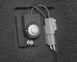
Disconnect the seat bar sensor connector (Item 1) [A].
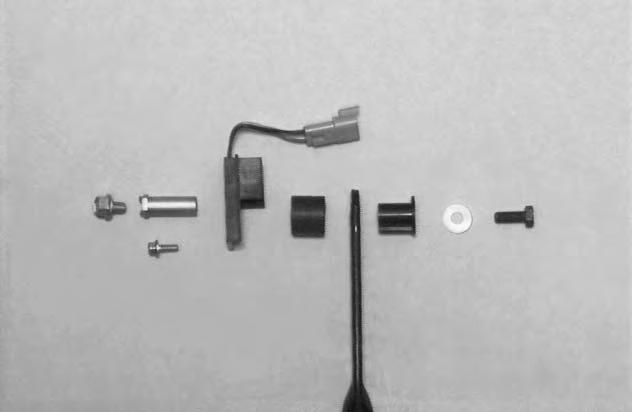
Remove the mounting bolt (Item 1) [B] from the pivot bushing.
Installation: Tighten the mounting bolt to 25–28 ft.–lbs. (34–38 Nm) torque.
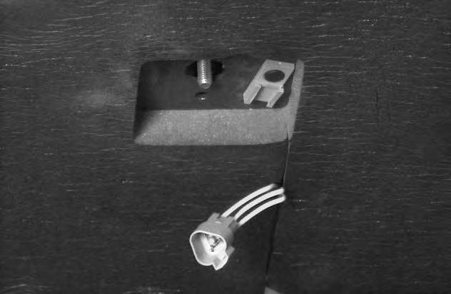
Remove the sensor mounting bolt (Item 2) [B] and nut.

Be careful to not overtighten the sensor mounting bolt and nut to prevent breakage of the sensor.
Installation: Be sure the tabs on the pivot bushing are positioned in the slotted hole (Item 1) [C] of the operator cab as shown.
Pull the seat bar back and remove the assembly as follows:
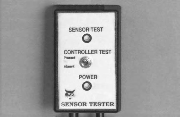
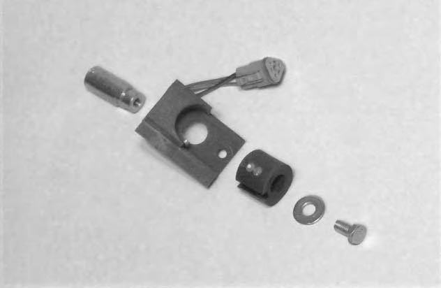
NOTE:The sensor assembly [D] is shown removed from the operator cab for clarity purpose only. The sensor assembly can be removed without removing the seat bar from the operator cab.
Remove the pivot bushing mounting bolt (Item 1)[D] and washer (Item 2) [D] from the pivot bushing (Item 3) [D]
Installation: Tighten the pivot bushing mounting bolt to 180–200 in.–lbs. (21–23 Nm) torque.
Remove the pivot bushing (Item 3) [D], sensor (Item 4) [D], magnet (Item 5) [D] and plastic bushing (Item 6) [D] from the seat bar.
Inspect all parts for damage and wear and replace if necessary.
Reverse the removal procedure to install the seat bar sensor.
Refer to Page 5–1 for seat bar removal and installation procedure.
SEAT BAR SENSOR (Cont’d)

Seat Bar Sensor Test
Use MEL1428 Sensor Tester for the following procedure: Turn the key to the ON position. DO NOT START THE ENGINE


Disconnect the seat bar sensor connector (Item 1) [A]
Connect
The power light (Item 1) [C] on the sensor tester will illuminate.
Lower the seat bar. The sensor test light (Item 1) [D] should illuminate.
Raise the seat bar. The sensor test light (Item 1) [D] should go off.
If the above tests fails, there is a problem with the seat bar sensor.
Refer to Page 8–3 for the correct procedure to inspect the Seat Bar Sensor.
Refer to Page 5–1 for seat bar removal and installation procedure.
Seat Sensor
Removal and Installation
Raise the loader operator cab. (See Page 1–1.)
Locate the seat sensor beneath the operator cab.
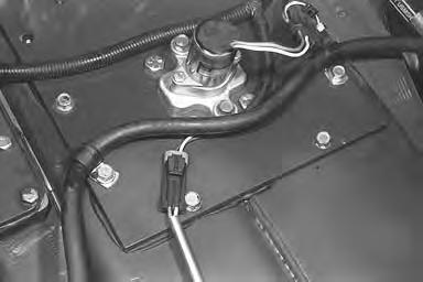
Remove the sensor connector (Item 1) [A] from the holder.
Disconnect the sensor connector (Item 1) [A].

Remove the magnet collar mounting bolt (Item 2) [A] & [B], washer (Item 3) [A] & [B] and magnet (Item 4) [A] & [B] from the sensor (Item 5) [A] & [B]
DO NOT overtighten the magnet mounting bolt to prevent damage to the magnet.
Remove the sensor mounting bolt (Item 6) [A] and nut.
Be careful to not overtighten the sensor mounting bolt and nut to prevent breakage of the sensor.
Remove the sensor (Item 5) [A] & [B].
NOTE:Be sure not to lose the magnet collar alignment pin (Item 6) [B] which is located in the sensor (Item 5) [B] when removing the sensor.
Remove the threaded bushing (Item 7) [B] from the seat track mounting bolt (Item 1) [C]
Inspect all parts for damage and wear and replace if necessary.
Reverse the removal procedure to install the seat sensor. Refer to Page 5–1 for seat removal and installation procedure.
SEAT SENSOR (Cont’d)
Seat Sensor Test
Use MEL1428 Sensor Tester for the following procedure: Turn the key to the ON position. DO NOT START THE ENGINE
Disconnect the seat sensor connector (Item 1 – Inset) [A]
Connect MEL1428 Sensor Tester (Item 2) [A] inline as shown to the seat sensor.
The
Sit on the operator seat. The sensor test light(Item 1) [C] should illuminate.
Get off the operator seat. The sensor test light (Item 1)[C] should go off.
If the above tests fail, there is a problem with the seat sensor.
Refer to Page 8–14 for the correct procedure to inspect the Seat Sensor.
Refer to Page 5–1 for seat removal and installation procedure.
Traction Lock
Removal and Installation
Avoid Injury Or Death
Do not modify the electrical wiring connected to the traction lock solenoid or any part of the traction lock system. The traction lock provides the locking function of the parking brake. Service work on the traction locksystem should only be performed by a qualified technician. Use only genuine Melroe parts if repair is necessary.
W–2165–0195
Raise the loader operator cab. (See Page 1–1.)
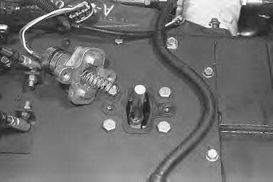
Remove the Do Not Modify sta–strap (P/N 6665527) from the electric solenoid connector (Item 1) [A].
Installation: Install a new Do Not Modify sta–strap (P/N 6665527) on the electric solenoid connector.
Remove the two mounting bolts (Item 2) [A] from the electric solenoid mounting bracket.
Installation: Tighten the mounting bolts to 25–28 ft.–lbs. (34–38 Nm) torque. Be sure the solenoid mounting bracket is installed in the same position. The solenoid mounting surface has a slight angle which tips the top of the solenoid toward the front of the loader when installed correctly.
Remove the electric solenoid and bracket assembly from the chaincase cover [B]
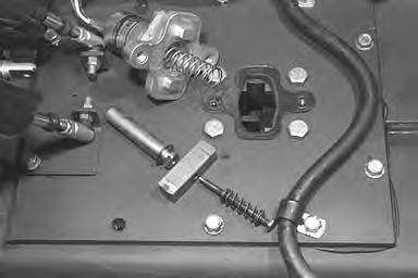

Remove and inspect the compression spring (Item 1)[B] for wear or damage. Replace if necessary. The spring may also stay with the shaft when the electric solenoid and bracket are removed from the chaincase.
Installation: Install the compression spring (Item 1) [B] on the collar located on the electric solenoid.
Remove the traction lock assembly (Item 1) [C] from the chaincase.
Remove the shaft mounting bolt (Item 1)[D], washer and spring from the assembly shaft (Item 2) [D]. Remove the wedge (Item 3) [D] and inspect all parts for damage or wear. Replace if necessary.
Installation: Thoroughly clean and dry the shaft mounting bolt (Item 1) [D], the shaft (Item 2) [D] and wedge (Item 3) [D]. Use LOCTITE #242 when assembling these parts to the traction lock assembly.
Failure to use LOCTITE may allow the traction lock assembly to loosen up which can cause damage to the traction lock system.
I–2090–1095
Refer to Page 8–1 for the traction lock inspection procedure.
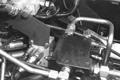
LIFT LOCK BY–PASS VALVE Removal and Installation
Never work on a machine with the lift arms up unless the lift arms are secured by a lift arm support device. Failure to use an approved lift arm support device can allow the lift arms or attachment to fall and cause injury or death.
When making repairs on hydrostatic and hydraulic systems, clean the work area before disassembly and keep all parts clean. Always use caps and plugs on hoses, tubelines and ports to keep dirt out. Dirt can quicklydamage the system.
Raise the loader lift arms and install an approved lift arm support device. (See Page 1–1.)
Install jackstands under the rear corners of the loader.
Raise the loader operator cab. (See Page 1–1.)
Drain the hydraulic fluid reservoir. (See Page 2–1.)
The lift lock by–pass valve (Item 1) [A] is located under the right side of the control panel.

Remove the engine speed control. (See Page 7–1.) This procedure is optional.
Remove the control panel. (See Page 3–1.) This procedure is optional.
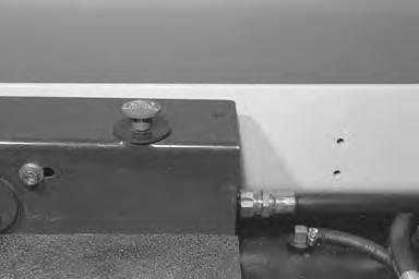
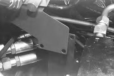
If you choose not to remove the engine speed control and control panel, the lift arm by–pass control knob (Item 1) [B] will need to be removed from the control panel.
Hold the by–pass control knob (Item 1)[B] and loosen the jam nut (Item 2) [B] on the by–pass valve shaft.
Remove the by–pass control knob and jam nut from the valve shaft.
Remove the rubber washer (Item 3) [B]
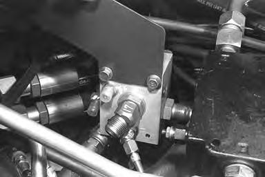
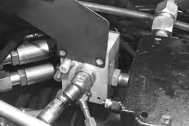
Disconnect the (5) tubelines from the lift lock by–pass valve (Item 1) [C].
Remove the (2) mounting bolts and nuts from the liftlock by–pass valve, that are located on the outside of the frame.

Installation: Tighten the (2) mounting bolts and nuts to 180–200 in.–lbs. (21–23 Nm) torque.
Refer to Page 8–1 for lift arm by–pass control inspection procedure.
Always clean up spilled fuel or oil. Keep heat, flames, sparks or lighted tobacco away from fuel and oil. Failure to use care around combustibles can cause explosion or fire which can result in injury or death.
W–2103–1285
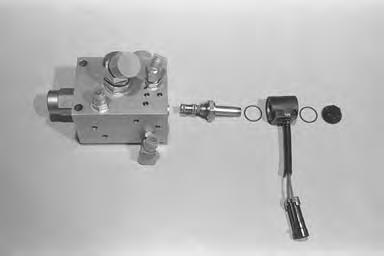
Disassembly and Assembly
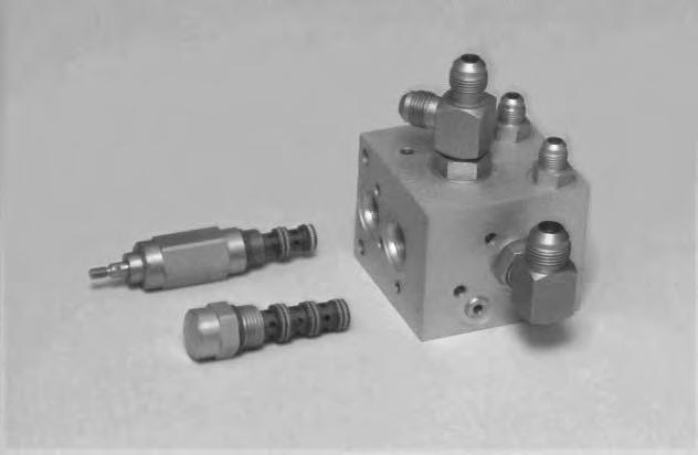
Remove the by–pass valve (Item 1) [A] from the valve block. Inspect the by–pass valve fordamage and replace if necessary.
Remove the check valve (Item 2)[A] from the valve block. Inspect the check valve for damage and replace if necessary.
Inspect the hydraulic fittings on the valve block for damage and replace if necessary.
Tilt Lock Valve
Removal and Installation
Never work on a machine with the lift arms up unless the lift arms are secured by a lift arm support device. Failure to use an approved lift arm support device can allow the lift arms or attachment to fall and cause injury or death.
When making repairs on hydrostatic and hydraulic systems, clean the work area before disassembly and keep all parts clean. Always use caps and plugs on hoses, tubelines and ports to keep dirt out. Dirt can quicklydamage the system.
I–2003–0284
Place jackstands under the rear corners of the loader.
Raise the loader lift arms and install the lift arm support device. (See Page 1–1.)
Raise the loader operator cab. (See Page 1–1.)
Drain the hydraulic fluid reservoir. (See Page 2–1.)
NOTE:Mark all tubelines for ease of installation.
The tilt lock valve (Item 1)[A] is located directly above the rear chaincase cover.

Disconnect the P2 port tubeline (Item 1) [B] and the B1 port tubeline (Item 2) [B] from the tilt lock valve.
Avoid Injury Or Death
Do not modify the electrical wiring connected to the tilt lock valve solenoid. Service work for the tilt lock valve should be performed by a qualified technician. Use only genuine Melroe parts if repair to the BICS ™is necessary.

W–2166–0195
Remove the Never Modify sta–strap (P/N 6665527) from the electric solenoid connector (Item 3) [B]
Installation: Install a new Never Modify sta–strap (P/N 6665527) on the electric solenoid connector (Item 3) [B]
Disconnect the X port tubeline (Item 1) [C] from the tilt lock valve.
Disconnect the PT port tubelines (Item 1)[D] from the tee fitting located on the back of the tilt lock valve.
Remove the tilt lock valve mounting bolts (Item 2)[D] and nut and move this to PP.
TILT LOCK VALVE (Cont’d)
Removal and Installation (Cont’d)
Disconnect the PP port hose (Item 1)[A] from the tilt lock valve.
Always clean up spilled fuel or oil. Keep heat, flames, sparks or lighted tobacco away from fuel and oil. Failure to use care around combustibles can cause explosion or fire which can result in injury or death.
TILT LOCK VALVE (Cont’d)
Disassembly and Assembly
Remove the solenoid mounting nut (Item 1)[A], solenoid (Item 2) [A] and solenoid valve (Item 3) [A] from the tilt lock valve.
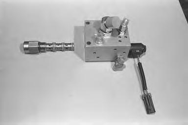
Remove the check valve (Item 1) [B] from the lift lock valve.
Assembly: Tighten the solenoid mounting nut to 80–90 in.–lbs. (9–10 Nm) torque.
Inspect the solenoid valve, check valve and hydraulic fittings for damage or wear. Replace if necessary.
Refer to Page 8–1 for lift arm by–pass control inspection procedure.
Skid Steer Loader Specifications
Dimensions are given for loader equipped with standard tires and dirt bucket and may vary with other bucket types. All dimensions are shown in inches. Respective metric dimensions are given in millimeters enclosed by parentheses.
Where applicable, specification conform to SAE or ISO standards and are subject to change without notice.
Changes of structure or weight distribution of the loader can cause changes in control and steering response and can cause failure of the loader parts.
CONTROLS
Vehicle Steering Direction and Speed controlled by two hand levers. Loader Hydraulics
Lift and Tilt Controlled by separate foot pedals.
Front Auxiliary Controlled by lateral movement of RH steering lever.
Rear Auxiliary (optional) Controlled by lateral movement of LH steering lever.
Engine Hand lever throttle: Key–type start switch and shutdown.
Starting Aid Push button ether start system . . . . .
Service Brake Two independent hydrostatic systems controlled by two hand . . . . . . . .
. . . . . . . . . . . operated steering levers.
Secondary Brake One of the hydrostatic transmissions
Parking Brake Mechanical Disc, foot operated pedal.
ENGINE
Make/Model Perkins/4.236 . . . . . . . . . . . . . . . . . . . . . . . .
Fuel/Cooling
Horsepower (SAE)
Diesel/Liquid
Gross: 74 HP (55 kW) Net: 71 Hp (53 kW)
Maximum Governed RPM 2200 RPM
Torque @ 1300 RPM (SAE)
Gross: 201 ft.–lbs. (272 Nm) Net: 194 ft.–lbs. (263 Nm) . . . . . . . . . .
Number of Cylinders Four . . . . . . . . . . . . . . . . .
Displacement 235.9 cu. in. (3,86 L)
Bore/Stroke 3.875/5.00 (98,4/127)
Lubrication Pressure System W/Filter
Crankcase Ventilation Open System Air Cleaner Dry replaceable cartridge w/safety element . . . . . . . . . . . . . . . . .
Compression
HYDRAULIC SYSTEM
Pump Engine Driven, Piston Type
Pump Capacity 25.0 GPM (95 L/min.) @ 2300 RPM
Pump CompensatorSetting
2400 PSI (16547 kPa) @ Zero Flow
Hydraulic Replaceable #4 micron element
Charge Replaceable #3 micron element
Hydraulic Cylinders Doubleacting; Bore Diameter:
(76,2)
Control Valve
21.46 (545)
4–spool, Lift & Tilt open center series. Auxiliary circuit open center parallel. Float detent on lift, detent on front auxiliary, and bucket position on tilt circuit.
Fluid Lines SAE standard tubes, hoses & fittings
Fluid Type Bobcat Fluid (P/N 6563328). If fluid is not available, use
10W–30/10W–40 Class SE motor oil for temperature above 0°F (–18°C)
5W–30 Motor Oil for temperatures below 0 °F (–18° C) Hydraulic
ELECTRICAL Alternator 50 amp open frame w/integral regulator
Battery 12 volt, 1000 cold cranking amps. @ 0 °F. (–18°C);
180 minute reserve capacity
Starter 12 volt, Gear Reduction Type
Instrumentation
DRIVE SYSTEM
Gauges: Hourmeter, Voltmeter, Fuel, Engine Temperature.
Warning Lights: Engine Oil Pressure, Hydrostatic Charge Pressure, Hydrostatic Fluid Temperature & Hydrostatic Filter.
Hydrostatic 4 wheel drive Transmission
Main Drive reversing hydrostatic motors. Separate gear type charge pump. Final
Infinitely variable tandem hydrostatic piston pumps, driving 2 fully .
Double gear reduction & #120 HS endless roller chain & sprockets in sealed chaincase with oil lubrication
Inflate tires to MAXIMU M pressure shown on the side wall of the tire. DO NOT mix brands of tires used on the same loader.