5 minute read
TROUBLESHOOTING Chart


The following troubleshooting chart is provided for assistance in locating and correcting problems which are most common. Many of the recommended procedures must be done by authorized Bobcat Service Personnel only.
Check for correct function after adjustments, repairs or service. Failure to make correct repairs or adjustments can cause injury or death.
Problem Cause
The hydraulic system will not operate.
Slow hydraulic system action.
Hydraulic action is not smooth.
Lift arms go up slowly at full engine RPM.
The lift arms or Bob–Tach will move with the pedal in neutral position5, 11
The lift arms come down with the pedal in the neutral position.
The bucket does not self–level. 16, 17, 18
The bucket will partially self–level.
The bucket has no power to roll forward.
The bucket does not roll back.
Key To Correct The Cause
1.The fluid level is not correct.
2.The pedal linkage is disconnected.
3.The hydraulic pump has defect.
4.Pressure compensator valve has a defect.
5.The pedal linkage is not adjusted correctly.
6.Drive belt is loose or broken.
16, 17
18
17
7.Check right and left hand auxiliary levers for neutral position.
8.Suction leak in the hydraulic system.
9.Fluid is cold.
10.Using the loader for more than its rated capacity.
11.Spool in the valve section is not centering or the centering spring is broken.
12.Internal leak at the lift cylinder(s).
13.External leak at the lift cylinder(s).
14.Port relief seal is leaking.
15.Load check has a defect in the valve section.
16.Check the flow divider in the bucket position valve.
17.Check the unloading spool in the bucket position valve.
18.Check the relief valve in the bucket position valve.
Hydraulic System Information
When making repairs on hydrostatic and hydraulic systems, clean the work area before disassembly and keep all parts clean. Always use caps and plugs on hoses, tubelines and ports to keep dirt out. Dirt can quicklydamage the system.
I–2003–0284
Flare Connections
Use the following procedure to tighten the flare fitting: Tighten the nut until it makes contact with the seat. Make a mark across the flats of both the male and female parts of the connection [A].
Use the chart to find the correct tightness needed [B]. If the fitting leaks after tightening, disconnect it and inspect the seat area for damage.
O–ring Face Seal Connection
When the fitting is tightened, you canfeel when the fitting is tight to eliminate leakage caused by under or over torqued fittings. Use Vaseline petroleum jelly to hold the O–ring in position until the fittings are assembled [C]
Straight Thread O–ring Fitting
Lubricate the O–ring before installing the fitting. Loosen the jam nut and install the fitting. Tighten the jam nut until the washer is tight against the surface [D]
Tubelines and Hoses
Replace any tubelines that are bent or flattened. They will restrict flow, which will slow hydraulic action and cause heat.
Replace hoses which show signs of wear, damage or weather cracked rubber.
Always use two wrenches when loosening and tightening hose or tubeline fittings.
of Both Nuts
Lift Cylinder
Checking the Lift Cylinder(s)
NOTE:With the bucket attached and the the boom raised to maximum height. The maximum cylinder drift allowed is 1.3 inches (33 mm) in 10 min. Measurement will be taken at cylinder lift rod.
Lower the lift arms. Stop the engine. Pull up on the lift arm by–pass control and move the lift pedal to release the hydraulic pressure. Raise the seat bar
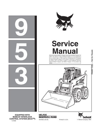
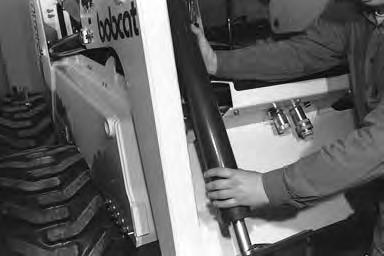
The lift cylinder has to be moved forward to disconnect the hose [A] at the base end of the cylinder. See procedure below for Removal and Installation of the Lift Cylinder.
Disconnect the hose which goes to the base end of the cylinder [A]
Put a plug in the hose [B]
Diesel fuel or hydraulic fluid under pressure can penetrate skin or eyes causing serious injury. Fluid leaks under pressure may not be visible. Use a piece of cardboard or wood to find leaks. Do not use your bare hand. Wear safety goggles. If fluid enters skin or eyes, get immediate medical attention.
W–2074–1285
Start the engine. Push the top of the lift pedal forward. If there is fluid leakage from the open port, remove the lift cylinder for repair.


Repeat this procedure to check the other lift cylinder.
Removal and Installation
Lower the lift arms. Stop the engine. Pull up on the lift arm by–pass control and move the lift pedal to release the hydraulic pressure. Raise the seat bar
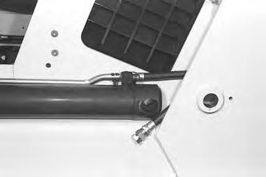
Put the lift pedal in the detent float position. Put a jack under the Bob–Tach and raise the lift arms. Install a jackstand [C].
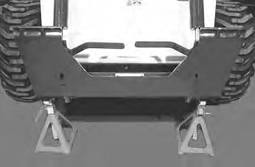
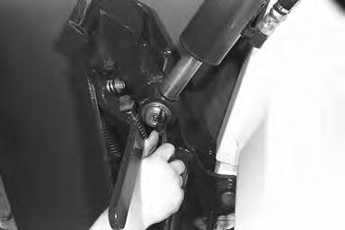
Remove the bolt (Item 1) [D] at the rod end and baseend pins of the lift cylinder.
Installation: Tighten bolt to 190–240 in.–lbs. (21–27 Nm) torque.
LIFT CYLINDER (Cont’d)
Removal and Installation (Cont’d)
Use a puller and remove the rod end and base end pins from the lift cylinder [A]

Pull the lift cylinder forward. Mark the hoses for correct installation.
Disconnect both hoses [B]
Put plugs in the hose ends.
Remove the lift cylinder from the loader.
Installation
When the rod end and base end pins are installed, make sure to align the retainer plate as the pin is installed.
Tilt Cylinder
Checking the Tilt Cylinder(s)
Remove any attachment from the Bob–Tach. Roll the Bob–Tach fully back. Stop the engine. Activate the tilt pedal to release the hydraulic pressure.
Put a chain around the Bob–Tach frame and the lift arms to prevent the Bob–Tach from going forward when the hoses are disconnected [C]

Disconnect the hose which goes to the base end of the tilt cylinder and install a plug in the end of the hose [D]
Diesel fuel or hydraulic fluid under pressure can penetrate skin or eyes causing serious injury. Fluid leaks under pressure may not be visible. Use a piece of cardboard or wood to find leaks. Do not use your bare hand. Wear safety goggles. If fluid enters skin or eyes, get immediate medical attention.
W–2074–1285
Start the engine. Push the bottom of the tilt pedal. If there is fluid leakage from the open port, remove the tilt cylinder for repair.
Repeat this procedure to check the other tilt cylinder.

TILT CYLINDER (Cont’d) Removal and Installation
Put the Bob–Tach on the floor. Stop the engine.Pull up on the lift arm by–pass control and move the lift pedal to release the hydraulic pressure.

Mark the hoses for correct installation.
Disconnect both hoses at the tilt cylinder.
Put plugs in the ends of the hoses.
Remove the snap ring at the base end [A]
Remove the washer from the pivot pin [B]
Remove
Remove the tilt cylinder by sliding off the pivot pins [D].
TILT CYLINDER (Cont’d)
Tilt Cylinder Base End Pivot Pin
Remove the bolt at the pivot pin(Item 1) [A]. Remove the washer.

Installation: When installing the bolt, tighten to 220–245 ft.–lbs. (298–332 Nm) torque.
Install

Remove the bolt and remove the pin (Item 1)[C] from the lift arms.

HYDRAULIC CYLINDER REPAIR Disassembly
NOTE:The following procedure can be used for both the lift and tilt cylinders. The toolslisted will be for either the lift or tilt cylinders.
The tools listed will be needed to do the following procedure:
MEL1075 – Gland Nut Wrench
Put the base end of the cylinder in a drain pan. Move the rod in and out to remove the fluid from the cylinderbarrel.
Put the base end of the cylinder in a vise. Remove the end cap from the cylinder using the special tool [A]
Remove the rod with the end cap and piston from the cylinder barrel.
The tilt cylinder is a cushion type cylinder and has a tapered piston [B].
The lift cylinder has a long sleeve on the rod [C].
HYDRAULIC CYLINDER REPAIR (Cont’d)
Disassembly (Cont’d)
Remove the piston from the rod [A]
Remove the end cap from the rod [B].
Remove the O–ring and back–up washer from the end cap [C].
Remove the wiper seal from the end cap [D]