14 minute read
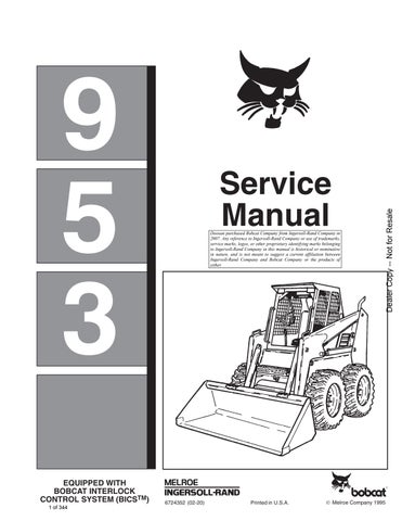
AIR CLEANER SERVICE


Replacing Filter Element
See the Service Schedule Page 1–3 for the interval to service the air cleaner system.
Check the air intake hoses for wear. If the air cleaner is damaged, check all the connections.
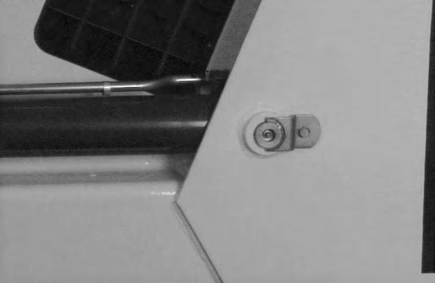
Replace the large (outer) filter element when the restriction indicator reads more than 22 inch H20 (Item 1) [A]
Replace the inner filter every third time the outer filter is replaced or when the restriction indicator reads 15 inch H20 at full engine RPM after the outer filter has been replaced.
Use the following procedure to replace the filter element(s):
NOTE: Before replacing the filter element, push the button (Item 2) [A] on the restriction indicator and start the engine. Run at full RPM. If readings are less than 22 inch H20 do not replace the filter elements.
Stop the engine and open the rear door. Raise the rear grill.
Service the air cleaner as follows:
Remove the dust cover wing nut (Item 1) [B].

Remove the dust cover [B].
Remove the wing nut (Item 1) [C] at the large filter element.
AIR CLEANER SERVICE (Cont’d)

Replacing Filter Element (Cont’d)
Remove the large filter element [A].
NOTE: Make sure all sealing surfaces are free of dirt and debris.
Install the new filter element and tighten the wing nut. Install the dust cover and tighten the wing nut.

Only replace the inner filter elemtent (Item 1) [B] under the following conditions:
Replace the inner filter element every thrid time the outer filter is replaced.
When the retriction indicator reads 15 inch H20 at full engine RPM, only after the outer filter element has been replaced.
Remove the inner filter (Item 1) [B] wing nut.
Remove the inner filter.
Install a new filter element and tighten the wing nut.
Fuel System
Fuel Specifications
Use only clean, high quality diesel fuel, Grade No. 1 or Grade No. 2 .
The following is one suggested blending guideline which should prevent fuel gelling problems:
We recommend an operator contact their fuel supplier for local recommendations.
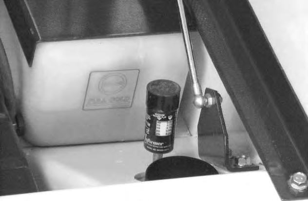
Filling the Fuel Tank
Stop and cool the engine before adding fuel. NO SMOKING! Failure to obey warnings can cause an explosion or fire.
Remove the fuel fill cap (Item 1) [A]
Use a clean, approved safety container to add fuel of the correct specifications. Add fuel only in an area that has free movement of air and no open flames or sparks. NO SMOKING! [B].
Install and tighten the fuel fill cap [A]
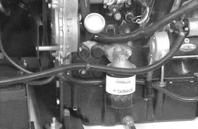
Fuel Filter
S/N 513111559 & Below
S/N 513115072 & Below
Always clean up spilled fuel or oil. Keep heat, flames, sparks or lighted tobacco away from fuel and oil. Failure to use care around combustibles can cause explosion or fire which can result in injury or death.
See the Service Schedule Page 1–3 for the service interval when to remove the water from the fuel filter.

Loosen the drain plug (Item 1) [C] or [D] at the bottom of the filter element to drain any water from the filter.
Tighten the drain plug.
S/N 513111560 & Above
S/N 513115073 & Above
FUEL SYSTEM (Cont’d)
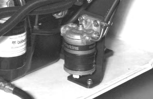
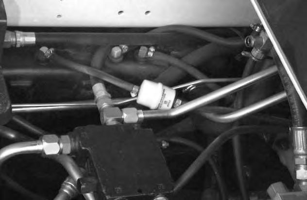
In–Line Fuel Filter
See the Service Schedule Page 1–3 for the correct service interval.
The In–Line fuel filter (Item 1) [A] is located at the fuel tank.
To replace the In–Line fuel filter, raise the operator cab. (See Page 1–7.)
Loosen the hose clamps. Remove the in–line fuel filter and replace with a new filter.
Engine Lubrication System
Checking Engine Oil
Check the engine oil level every day.
Remove the dipstick (Item 1) [A].
Keep the oil level between the marks on the dipstick[B]
Use a good quality motor oil that meets API Service Classification of CD, CE or better.
RECOMMENDED SAE VISCOSITY NUMBER (LUBRICATION OILS FOR ENGINE CRANKCASE)
TEMPERATURE RANGE ANTICIPATED BEFORE NEXT OIL CHANGE
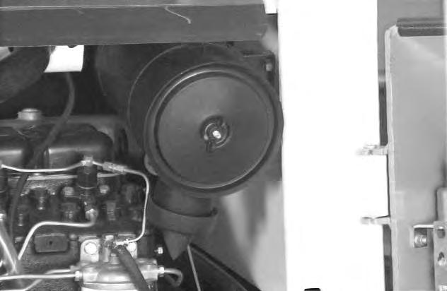
Replacing of Oil and Filter
See the Service Schedule Page 1–3 for the service interval for replacing the engine oil and filter.
Run the engine until it is at operating temperature. Stop the engine.
Open the rear door. Remove the drain plug (Item 1) [C] Drain the oil into a container.
Remove the oil filter (Item 1) [D]
Clean the filter housing surface. Put clean oil on the new oil filter gasket. Install the filter and hand tighten.
Install and tighten the drain plug.
Remove the filler cap (Item 2) [D] from the oil fill tube. Put 7.0 qts. (6,6 L) of oil in the engine. (See Oil Chart.)
Start the engine and let it run for several minutes. Stopthe engine.
Check for leaks at the oil filter and check the oil level. Add oil as needed if it is not at the top mark on the dipstick.
Engine Cooling System
Checking the Coolant Level
Check the cooling system every day to prevent over–heating, loss of performance or engine damage.
Wear safety glasses to prevent eye injury when any of the following conditions exist:
• When fluids are under pressure.
• Flying debris or loose material is present.
• Engine is running.
• Tools are being used.
Open the rear door. Raise the rear grill.
W–2019–1285
Check the coolant level in the coolant recovery tank (Item 1) [A].

The coolant recovery tank must be 1/3 full.
Propylene Glycol
Add premixed coolant; 47% water and 53% propylene glycol to the recovery tank if the coolant level is low.
One gallon and one pint of propylene glycol mixed with one gallon of water is the correct mixture of coolant to provide a –34°F (–37°C) freeze protection.
Use a refractometeror coolant test strips (P/N 6724274) to check the condition of propylene glycol in your cooling system.
Never mix propylene glycol with ethylene glycol.
Cleaning the Cooling System
Raise the rear grill [A].
Use air pressure or water pressure to clean the top of the oil cooler [A]
Raise the oil cooler and clean the top of the radiator [B].
Check cooling system for leaks.
ENGINE COOLING SYSTEM (Cont’d)

Removing Coolant From the Cooling System
Do not remove radiator cap when the engine is hot. You can be seriously burned.
W–2070–1285
Open the rear door. Open the rear grill. Remove the radiator cap (Item 1) [A].

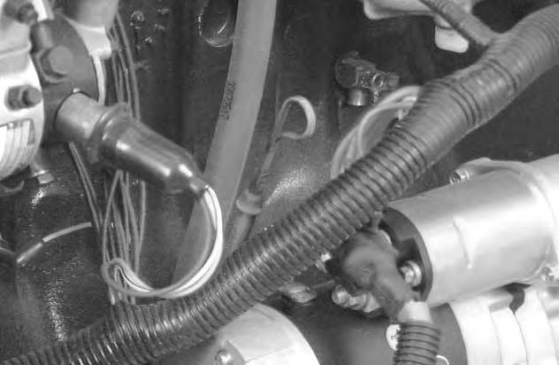
Connect a hose to the engine block drain valve (Item 1) [B]. Open the drain valve and drain the coolant into a container.
After all the coolant is removed, close the drain valve.
NOTE: Protect the cooling system by adding premixed coolant to the system. (See Page 1–16.) This mixture will protect the cooling system to –34oF. (–36oC.)
Mix the coolant in a separate container. (See Specifications for correct capacity, Page 9–1.)
Fill the radiator with the premixed coolant. Install the radiator cap.
Fill the coolant recovery tank 1/3 full.
Run the engine until it is at operating temperature. Stop the engine.
Check the coolant level in the recovery tank when cool. Add coolant to the recovery tank as needed.
Alternator Belt
Adjusting the Alternator Belt
Stop the engine.
Open the rear door.
Loosen the alternator mounting bolt (Item 1) [A]
Loosen the adjustment bolt (Item 2) [A]
Move the alternator until the belt has 5/16 inch (8,0 mm) movement at the middle of the belt span with 15 lbs. (66 N) of force [B].

Tighten the adjustment bolt and mounting bolt.
Close the rear door.
USING A BOOSTER BATTERY (JUMP STARTING) Procedure
If it is necessary to use a booster battery to start the engine, BE CAREFUL! There must be one person in the operator’s seat and one person to connect and disconnect the battery cables.
The ignition must be in the OFF position. The booster battery to be used must be 12 volt.
Keep arcs, sparks, flames and lighted tobacco away from batteries. When ”jumping” from booster battery make final connection (negative) at engine frame.
Do not jump start or charge a frozen battery. Warm battery to 60 oF. (16oC.) before connecting to a charger. Unplug charger before connecting or disconnecting cables to battery.
Battery gas can explode and cause serious injury.
W–2066–0490
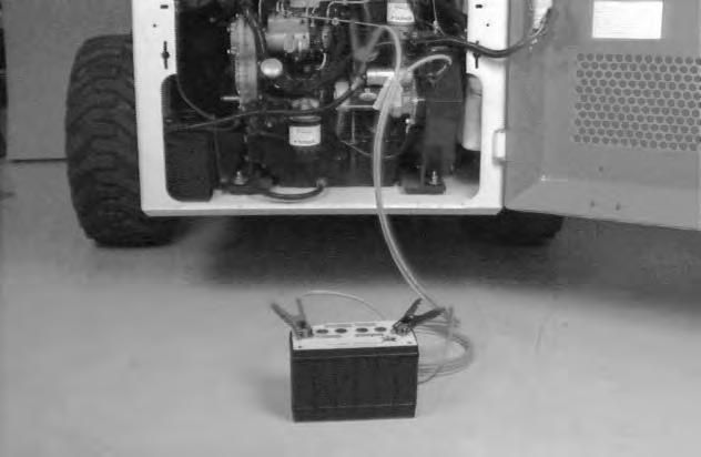
Connect the end of the first cable (Item 1) [A] to the positive (+) terminal of the booster battery. Connect the other end of the same cable (Item 2) [A] to the positive terminal on the starter.
Connect the end of the second cable (Item 3) [A] to the negative (–) terminal of the booster battery. Connect the other end of the same cable (Item 4) [A] to the engine. Keep cables away from moving parts. Start the engine. See Operation & Maintenance Manual for Cold Temperature Starting Condition.
After the engine has started, remove the ground (–) cable (Item 4) [A] first. Remove the cable from the positive terminal on the starter.
Damage to the alternator can occur if:
* Engine is operated with battery cables disconnected.
* Battery cables are connected when using a fast charger or when welding on the loader (Remove both cables from the battery).
* Extra battery cables (booster cables) are connected wrong.
I–2023–1285
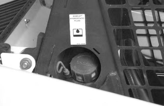
HYDRAULIC/HYDROSTATIC SYSTEM Checking and Adding Fluid
Use only recommended fluid in the hydraulic system. (See Specifications Section for the correct fluid Page 9–1.)

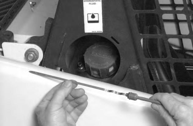
To check the reservoir, use the following procedure:
Put the Bobcat loader on a level surface. Lower the lift arms and tilt the Bob–Tach fully back.
Stop the engine.
Remove the dipstick (Item 1) [A]
The fluid level must be between the marks on the dipstick [B]
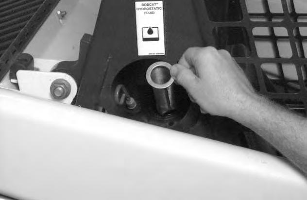
If fluid is needed, remove the fill cap (Item 2) [A]
Add the fluid as needed to bring the level to the top mark on the dipstick [B]
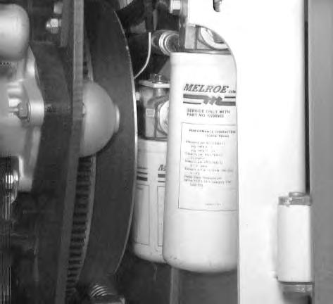
Hydraulic/Hydrostatic Filter Replacement
See the Service Schedule Page 1–3 for the correct service interval.
NOTE: Drive belt shield was removed for clarity.
Open the rear door.
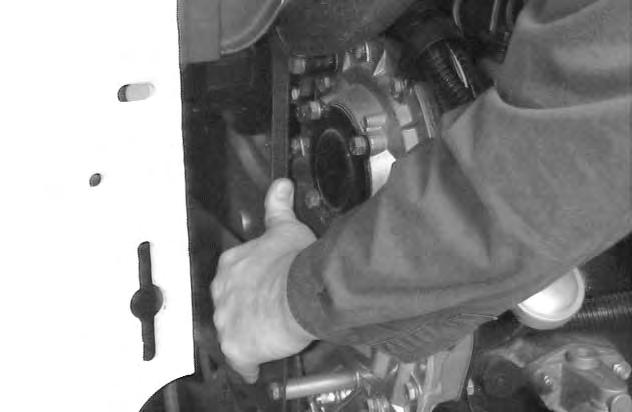
Use a filter wrench. Remove the filter elements (Items 1 & 2) [C]
Clean the surface of the filter housing where theelement seal contacts the housing. Put clean oil onthe rubber seal of the filter element.
Install and hand tighten the filter elements
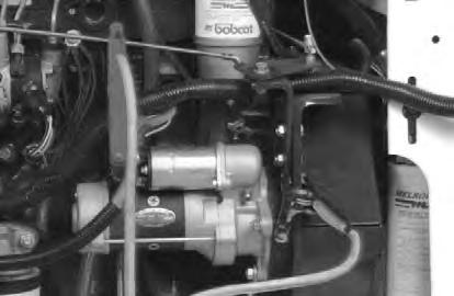
HYDRAULIC/HYDROSTATIC SYSTEM (Cont’d)
Case Drain Filter
See the Service Schedule Page 1–3 for the correct service interval.
Raise the operator cab. (See Page 1–7.)
Use a filter wrench. Remove the filter element (Item 1) [A]
Clean the surface of the filter housing where theelement seal contacts the housing. Put clean oil onthe rubber seal of the filter element.
Install and hand tighten the filter element.
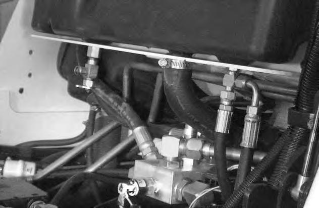
Hydraulic Fluid Replacement
See the Service Schedule Page 1–3 for the service interval.
The fluid must also be replaced if it becomes contaminated or after major repairs.
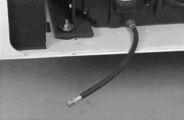
Remove the reservoir fill cap (Item 1) [B]
Raise the operator cab. Connect a 5/8 inch ID hose to the drain valve. Open the drain at the bottom of thereservoir (Item 1) [C]. Let the fluid flow into a container.

Close the drain when the reservoir is empty.
Remove the screen (Item 1)[D]. Wash the screen in clean solvent and install it in the fill pipe.
Remove the hydraulic/hydrostatic filter elements. (See Page 1–20.) Install new filter elements.
Add fluid to the reservoir until the fluid is at the top mark on the dipstick. (See the Specifications Section for type of fluid and capacity.) DO NOT fill above the top mark on the dipstick.
Lower the operator cab. Start the engine and operate the loader through the hydraulic and hydrostatic functions. Stop the engine. Check the fluid level again and add as needed.
Always clean up spilled fuel or oil. Keep heat, flames, sparks or lighted tobacco away from fuel and oil. Failure to use care around combustibles can cause explosion or fire which can result in injury or death. W–2103–1285
Spark Arrestor Muffler
Cleaning Procedure
See the Service Schedule Page 1–3 for service interval for cleaning the spark arrestor muffler.

Do not operate the loader with a defective exhaust system.
Stop the engine. Open the rear door and rear grill. Remove the plug (Item 1) [A] from the bottom of the muffler .
Start the engine and run for about 10 seconds while a second person, wearing safety glasses, holds a piece of wood over the outlet of the muffler.
Stop the engine. Install and tighten the plug. Lower the rear grill and close the rear door.
EXHAUST GAS PURIFIER (Optional)
Function
The Exhaust Gas Purifier, when installed on the 953 loader, provides a cleaner exhaust by burning excess carbon particles and gases emitted by the engine.
When the purifier is installed on a new loader, the purifier must be cleaned every 6 to 8 months.
Cleaning the Exhaust Gas Purifier
Remove the purifier from the engine on the loader.
Use air pressure to force any loose particles or debris from the purifier.
If soft carbon deposits are present, a pressure washer can be used to wash any remaining carbon deposits from the purifier.
NOTE:Do not place the nozzle of the air or pressure washer inside the purifier. Maximum pressure of 50 PSI (345 kPa) is allowed for the cleaning procedure.
Dry the purifier thoroughly with air.
When an engine is running in an enclosed area, fresh air must be added to avoid concentration of exhaust fumes. If the engine is stationary, vent the exhaust outside. Exhaust fumes contain odorless, invisible gases which can kill without warning.
W–2050–1285
Stop engine and allow the muffler to cool before cleaning the spark chamber. Wear safety glasses or goggles. Failure to obey can cause serious injury.
W–2011–1285
Never use machine in atmosphere with explosive dust or gases or where exhaustcan contact flammable material. Failure to obey warnings can cause injury or death.
W–2068–1285
This loader is factory equipped with a U.S.D.A. Forestry Service approved spark arrestor muffler. It is necessary to do maintenance on this spark arrestor muffler to keep it in working condition. The spark arrestor muffler must be serviced by dumping the spark chamber every 100 hours of operation.
If this machine is operated on flammable forest, brush or grass covered land, it must be equipped with a spark arrestor attached to the exhaust system and maintained in working order. Failure to do so will be in violation of California State Law, Section 4442 PRC.
Make reference to local laws and regulations for spark arrestor requirements.
I–2022–1285
Tire Maintenance
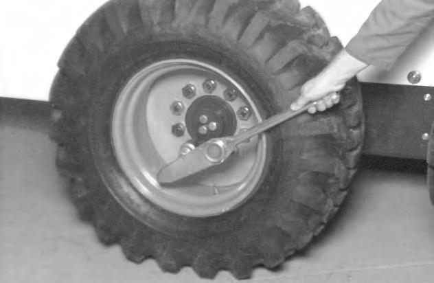
Wheel Nuts
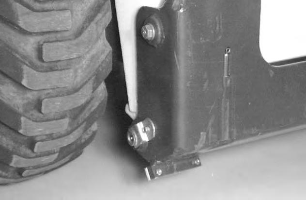
See the Service Schedule Page 1–3 for the service interval to check the wheel nuts. The correct torque is 105–115 ft.–lbs. (142–156 Nm) torque [A].
Tire Rotation
Check the tires regularly for wear, damage and pressure. (See Specifications, Page 9–1 for the correct tire pressure.)
Rear tires usually wear faster than front tires. To keep tire wear even, move the front tires to the rear and rear tires to the front [B]
It is important to keep the same size tires on each side of the loader. If different sizes are used, each tire will be turning at a different rate and cause excessive wear. The tread bars of all the tires must face the same direction.
Recommended tire pressure must be maintained to avoid excessive tire wear and loss of stability and handling capability. Check for the correct pressure before operating the loader.
Tire Mounting
Tires are to be repaired only by an authorized person using the proper procedures and safety equipment. Tires and rims must always be checked for correct size before mounting. Check rim and tire bead for damage.
The rim flange must be cleaned and free of rust. The tire bead and rim flange must be lubricated with a rubber lubricant before mounting the tire, avoid excessive pressure which can rupture the tire and cause serious injury or death. During inflation of the tire, check the tire pressure frequently to avoid over inflation.
Do not inflate tires above specified pressure. Failure to use correct tire mounting procedure can cause an explosion which can result in injury or death.
W–2078–1285
I–2057–0794
FINAL DRIVE TRANSMISSION (CHAINCASE)
Checking and Adding Oil
The chaincase contains the final drive sprockets and chains and uses the same type of oil as the Hydraulic/Hydrostatic System. (See Specifications Section, Page 9–1.)
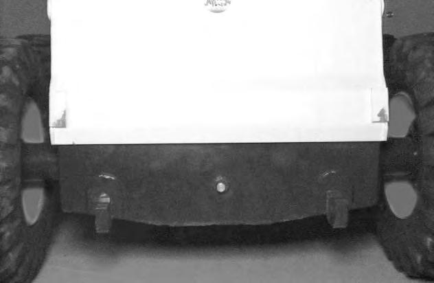
To check the chaincase oil level, use the following procedure:
Drive the loader on a level surface. Stop the engine. Remove the plug (Item 1) [A] from the front of the chaincase housing
If oil can be reached with the tipof the your finger through the hole the oil level is correct.
If the level is low, add oil through the check plug hole until the oil flows from the hole. Install and tighten the plug.
LUBRICATING THE LOADER Procedure
Lubricate the loader as specified in the Service Schedule Page 1–3 for the best performance of the loader.

Always use a good quality lithium based multi–purpose grease when you lubricate the loader. Apply the lubricant until extra grease shows.

Lubricate the following locations on the loader:

LUBRICATING THE LOADER (Cont’d)
Procedure (Cont’d)
5.Rod End Tilt Cylinder (Both sides) [A]
6.Bob–Tach Wedge (Both Sides) [B]
7.Bob–Tach Pivot Pin (Both Sides) [B]
Every 250 Hours: Add oil to the steering shaft two holes (Item 1) [C]. Add grease to the fitting (Item 2) [C].
REMOTE START SWITCH Procedure
The tool listed will be needed to do the following procedure:
MEL1429 – Remote Start Switch
Put jackstands under the front axles and rear corners of the frame before running the engine for service. Failure to use jackstands can allow the machine to fall or move and cause injury or death.
W–2017–0286
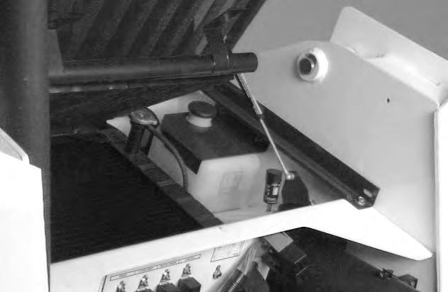
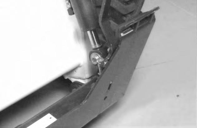
The Remote Start Switch (Item 1)[A] is required when the operator cab is in the raised position for service and the service technician needs to start the engine. The operator cab wire harness connectors must be separated from the engine wiring harness connector under the cab.

The remote start switch is required when the service technician is adjusting the steering linkage and checking the hydraulic/hydrostatic system.

Lift and block the loader. (See Page 1–4.)
Raise the lift arms and install an approved lift arm support device. (See Page 1–6.)
Raise the operator cab. (See Page 1–7.)
Connect the remote start switch to these connectors (Item 1) [B]
REMOTE START SWITCH (Cont’d)
Procedure (Cont’d)
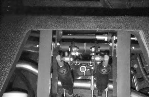
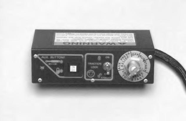
Put the traction lock override switch (Item 1)[A] in the ON position so the traction function is locked. The wheels are not able to turn.
Turn the key to the right and start the engine.
Move the traction lock override switch (Item 1) [B] to the OFF position so the traction function is unlocked. The wheels are now able to turn.
The auxiliary mode switch (Item 2) [B] is used to turn the front auxiliary quick couplers ON and OFF during relief pressure and flow tests.

Hydraulic System
HYDRAULIC SYSTEM (Cont’d)
(S/N 513111001 –11593)
(S/N 513115001 –15084)
(Printed February 1997)
FLUID RESERVOIR: 1
Cap . . . . 24.0 Qts (22,7 L)
Screen Filter. . . . . 60 Mesh
2OIL COOLER
3 FAN MOTOR. . . . . GEAR TYPE
4OIL COOLER BY-PASS:
5 100 PSI (690 kPa)
ORIFICE (Dia.) 0.092" (2,34 mm)
6TEMPERATURE SWITCH
200º F (93º C)
7TEMPERATURE SWITCH
230º F (110º C)
9TEMPERATURE SWITCH
100º F (38º C) Normally Open
23
5220 PSI (35991 kPa)
CHARGE PRESSURE VALVE:
@ 2200 RPM ENGINE SPEED PORT
2550 PSI (17582 kPa)
PORT RELIEF VALVE:
3500 PSI (24131 kPa)
12BY-PASS
10 FAN MOTOR BY-PASS: 1400 PSI (9653 kPa) 50
DIFFERENTIAL SWITCH:
PSI (345 kPa) 40 PSI (276 kPa)
25 MICRON FILTER
5 PSI (34 kPa)
BY-PASS VALVE:
20 PSI (136 kPa)
TILT CYLINDER CHECK VALVE 32
33 HYDROSTATIC MOTOR – R.H. SIDE FIXED DISPLACEMENT
18 19 20
HYDROSTATIC MOTOR – L.H. SIDE FIXED DISPLACEMENT
4 MICRON FILTER
IMPLEMENT PUMP:
25.0 GPM (95 L/min.)
HYDRAULIC/HYDROSTATIC SCHEMATIC 953 BICS (S/N 513111001 -11593)
(S/N 513115001 -15084)
(Printed February 1997) (MC-2203)
HYDRAULIC/HYDROSTATIC SCHEMATIC
953 BICS TM
(S/N 513111594 -14999
S/N 513115085 and Above
(Printed February 1997)
IMPLEMENT PUMP:
Cap . . . . 24.0 Qts (22,7 L) Screen Filter. . . . . 60 Mesh
2OIL COOLER
3 FAN MOTOR. . . . . GEAR TYPE
4OIL COOLER BY-PASS:
5 100 PSI (690 kPa)
ORIFICE (Dia.) 0.092" (2,34 mm)
6TEMPERATURE SWITCH
200º F (93º C)
7TEMPERATURE SWITCH
230º F (110º C)
9TEMPERATURE SWITCH
100º F (38º C) Normally Open
10 FAN MOTOR BY-PASS:
DIFFERENTIAL SWITCH:
BY-PASS VALVE:
20 PSI (136 kPa)
HYDROSTATIC MOTOR – L.H. SIDE FIXED DISPLACEMENT
ORIFICE (Dia.) 0.052" (1,32 mm)
4 MICRON FILTER
CHECK VALVE CRACK PRESSURE
5 PSI (34 kPa)
25.0 GPM (95 L/min.)
5220 PSI (35991 kPa)
2550 PSI (17582 kPa)
PORT RELIEF VALVE:
3500 PSI (24131 kPa)
HYDRAULIC/HYDROSTATIC SCHEMATIC 953 BICS (S/N 513111594 -14999)
(S/N 513115085 and Above)
(Printed February 1997) (MC-2319)