36 minute read
TROUBLESHOOTING Chart


The following troubleshooting chart is provided for assistance in locating and correcting problems. Many of the recommended procedures must be done by authorized Bobcat Service Personnel only.
Instructions are necessary before operating or servicing machine. Read Operation & Maintenance Manuals, Handbook and signs (decals) on machine. Follow warnings and instructions in the manuals when making repairs, adjustments or servicing. Check for correct function after adjustments, repairs or service. Failure to follow instructions can cause injury or death. W–2003–1289
Battery will not take a charge.
Alternator will not charge.
Starter will not turn the engine.
Key To Correct The Cause
1.Alternator belt is loose or damaged.
2.Battery connections are dirty or loose.
3.Battery is damaged.
4.The ground connection is not making a good contact.
5.The alternator is damaged.
6.The engine is locked.
7.The starter is damaged.
8.The wiring or the solenoid is damaged.
9.Check the fuses.
ELECTRICAL SYSTEM INFORMATION Description
The loader has a 12 volt, negative ground alternator charging system. The electrical system is protected by fuses located in the engine compartment. The fuses will protect the electrical system when there is an electrical overload. The reason for the overload must be found before starting the engine again.
Fuse Location
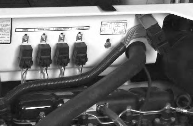
The electrical system for this model loader is protected by fuses (Item 1) [A] located in the engine compartment.
The fuse capacity and circuits are listed below [B] & [C]:
Battery
Checking the Battery
The tools listed will be needed to do the following procedure:
MEL10004 – Battery Tester
To make a safe and complete check of the battery seethe Battery Manual (P/N 6566047).
The Battery Manual has all the infomation and specifications needed for checking and servicing the battery. Replace the battery as needed.

Batteries contain acid which burns eyes and skin on contact. Wear goggles, protective clothing and rubber gloves to keep acid off body.
In case of acid contact, wash immediately with water for several minutes and get medical attention in case of eye contact.
W–2065–1286
DO NOT remove the vent caps from the battery while charging the battery. The battery has vent caps which will decrese the possiblity of the battery being exploded byan external spark.
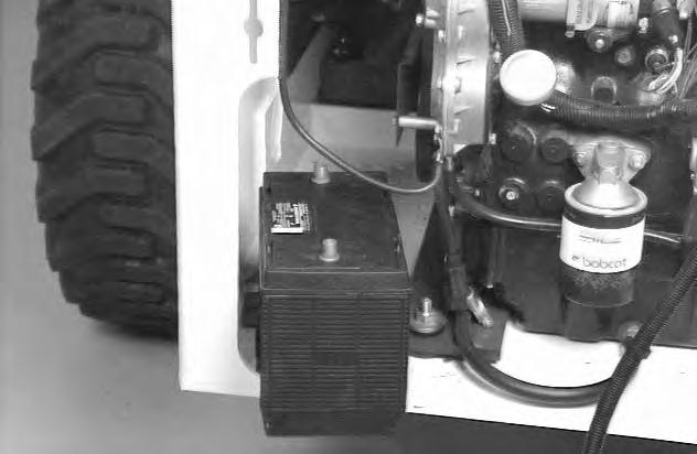
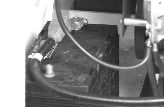
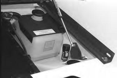
Removal and Installation
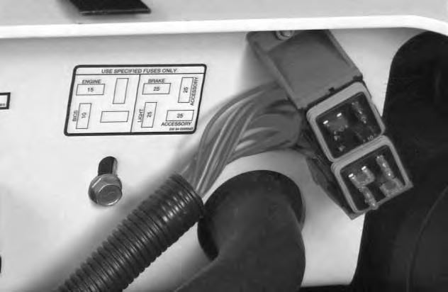
Disconnect the negative battery cable (Item 1) [A]. Always disconnect the negative cable first to prevent sparks.
Remove the nuts and bolts from the holddown clamp (Item 1) [B] and remove the holddown clamp.
Disconnect the positive battery cable (Item 1)[C] from the battery. Remove the battery from the loader [D]
Alternator
Alternator Output Test
Put jackstands under the front axles and rear corners of the frame before running the engine for service. Failure to use jackstands can allow the machine to fall or move and cause injury or death.
W–2017–0286
Test the alternator in the following sequence:
Alternator Output Test
Rectifier (Diode) Test
Alternator Regulator Test
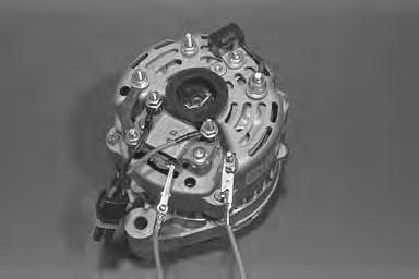
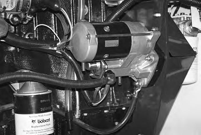
Blower box removed for photo clarity.
Lift and block the loader. (See Page 1–1.)
Disconnect the negative (–) cable from the battery.
Disconnect the red wire (Item 1) [A] from the alternator. Connect that wire to the negative (–) side of the ammeter.
Connect the positive (+) side of the ammeterto the output terminal on the alternator (Item 2) [A]
Disconnect the fuel stop solenoid connector.
Connect the negative (–) cable to the battery.
Turn on the lights and crank the engine for 30 seconds to discharge the battery.
Connect the fuel stop solenoid, start the engine and run at 2600 RPM.
The ammeter reading should be between 45–55 amps. @ 2600 RPM.
If the reading is low, remove the screws and pull the regulator cover away from the alternator.

Rectifier (Diode) Test
The alternator is removed from the loader for photo clarity purposes [B]
Disconnect the negative (–) cable from the battery. Install the wires in their original location on the back of the alternator.
Remove the regulator cover from the back of the alternator [B]
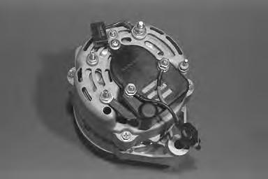
Connect a jumper wire (Item 1)[C] to the alternator output terminal and the regulator terminal.
Connect the battery negative (–) cable.
Start the engine and run at 2600 RPM.
If the reading is within 45–55 amps. at 2600 RPM replace the rectifier (diode) assembly or replace the alternator.
If the reading is low, do the Alternator Regulator Test.
ALTERNATOR (Cont’d) Alternator Regulator Test
When an engine is running in an enclosed area, fresh air must be added to avoid concentration of exhaust fumes. If the engine is stationary, vent the exhaust outside. Exhaust fumes contain odorless, invisible gases which can kill without warning.
W–2050–1285
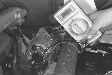
Connect the positive (+) voltmeter lead to the positive (+) battery terminal [A].
Connect the negative (–) voltmeter lead to the negative (–) battery terminal [A].
Start the engine and run at 1500–2000 RPM.
The voltmeter should read between 13.9–14.7 volts.
If the reading is low, stop the engine and disconnect the battery negative (–) cable.
The alternator is removed from the loader for clarity purposes [B]
Remove the wires from the back of the alternator.
Remove the regulator cover from the back of the alternator.
Install the wires on the back of the alternator.
Connect a jumper wire (Item 1) [B] from the brush terminal to the ground stud.
Connect the negative (–) battery cable and start the engine. Run at 1500 RPM.

If the voltmeter reading is 14.5 or above, replace the regulator.
If the voltmeter reading is below 14.5, repairor replace the alternator.
ALTERNATOR (Cont’d)
Removal and Installation
Damage to the alternator can occur if:
• Engine is operated with battery cables disconnected.

• Battery cables are connected when using a fast charger or when welding on the loader (Remove both cables from the battery).
• Extra battery cables (booster cables) are connected wrong.
I–2023–1285
Place jackstands under the rear corners of the loader.
Raise the lift arms and install an approved lift arm support device. (See Page 1–1.)
Raise the operator cab. (See Page 1–1.)
Disconnect the negative (–) cable from the battery.
Disconnect the red wire (Item 1) [A] from the alternator which comes from the battery.
Disconnect the wiring harness connector (Item 2) [A] from the alternator.
Remove the adjustment bolt (Item 3) [A] from the mounting bracket.
Remove the alternator belt from the alternator pulley.
Remove the mounting bolt (Item 4) [A]
Remove the alternator.
Adjusting the Alternator Belt
Stop the engine.
Raise the operator cab. (See Page 1–1.)
Loosen the alternator mounting bolt (Item 4) [A].
Loosen the adjustment bolt (Item 3) [A].
Move the alternator until the belt has 5/16 inch (8,0 mm) movement at the middle of the belt span with 15 lbs. (66 N) of force.
Tighten the adjustment bolt and mounting bolt.
Lower the operator cab.
ALTERNATOR (Cont’d)
Disassembly
Disassemble the alternator. (See Parts Identification[A].)
Remove the regulator cover and regulator.
Remove the four bolts holding halves together. Pry the halves apart.
Use a soft jaw vise to holdrotor while removing pulley nut. Remove front case half from the rotor using a plastic hammer.
Unsolder the stator leads from the rectifier. Remove the stator.

A
1. Nut 9. Rectifier (Diode)
2. Pulley 10. Case Half (Rear)
3. Fan 11. Condenser Assy.
12.
Stator Continuity Test

Use an ohmmeter to test the stator.
Touch the probes to two of the bare stator wires [B] Move one of the probes to the third wire.
The readings should be the same.
If there is no continuity, replace the stator.
Stator Ground Test
Touch one probe to a bare stator lead and the other probe to the bare metal surface of the stator [C].
There should be no continuity. Replace the stator if there is continuity.
ALTERNATOR (Cont’d)
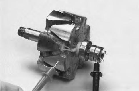
Rotor Continuity Test
Use an ohmmeter to test the rotor.
Touch the probes to the slip rings [A]
The ohmmeter should read between 3.0–33.0 ohms. If there is no continuity replace the rotor.
Rotor Ground Test
Touch one probe to one of the slip rings and the other probe to the rotor shaft [B]
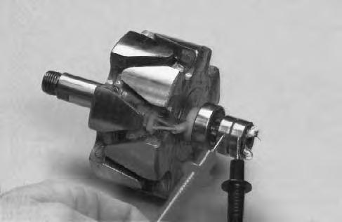
There should be no continuity. Replace the rotor if there is continuity.
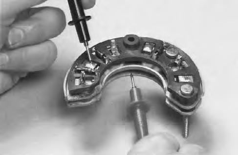
Rectifier Continuity (Diode) Test
NOTE:In the diode tests there should be continuity in one direction only. If the diode being tested shows no continuity or continuity in both directions, replace the rectifier assembly.
Touch the probes to the terminals of each diode and read the meter [C]
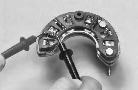
Reverse the probes to check the diode in the other direction.
There should be continuity in one direction only.
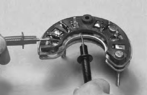
Touch one probe to the diode and the other probe to the connected heatsink and read the meter [D]
Reverse the probes to check the diode in the other direction.
There should be continuity in one direction only.
ALTERNATOR (Cont’d)
Rectifier Continuity (Diode) Test (Cont’d)
Touch one probe to the diode and the other probe to the connected heatsink and read the meter [A]
Reverse the probes to check the diode in the other direction.
There should be continuity in one direction only.
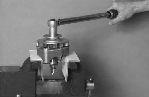
Assembly
Reverse the order of disassembly. Do not assemble the rear case half.
Place the rotor in soft jaws when tightening the shaftnut. Tighten to 50 ft.–lbs. (68 Nm) torque [B].
Install the rear case half and the remaining parts.
STARTER (S/N 11375 & Below)
Removal and Installation
Stop the engine and open the rear door.
Disconnect the negative (–) and positive (+) cables from the battery.
Remove the lower mounting bolt (Item 1)[A]. Remove the frame ground cable from the starter.
Disconnect the engine harness power wires and positive (+) battery cable starter solenoid terminal (Item 2) [A].
Disconnect the white wire and red wire (Item 3) [A] from the S termianl on the starter solenoid.
Remove the mounting bolts (Item 1) [B] form the starter.
Remove the starter from the engine.
Installation: Tighten the mounting bolts to 25–28 ft.–lbs. (34–38 Nm) torque.
Checking the Starter
The key switch must be in the OFF position.
The battery must be at full charge.
The cable connections on the battery must be clean and tight.
Connect a jumper wire between S terminal and BAT terminal [C].
If the starter turns but does not engage the flywheel and turn the engine, the starter drive has a defect.

Connect a jumper wire between the M terminal and the BAT terminal [D].
If the starter turns, the defect is in the solenoid.
If the starter does not turn, the starter is defective.
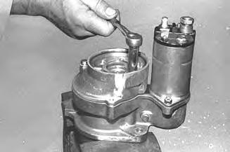
STARTER (S/N 11375 & Below) (Cont’d)
Disassembly and Assembly
Remove the starter thru–bolts [A].
Remove the screws for the brush holder [B]
Remove the starter end cap [C].
Remove the starter housing/armature assembly from the reduction gear drive [D].
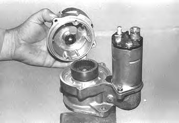
STARTER (S/N 11375 & Below) (Cont’d)
Disassembly and Assembly (Cont’d)
Remove the armature and brushes from the starter housing [A]
Remove the bolts from the reduction gear housing [B]
Remove the reduction gear housing [C].
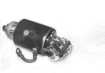
STARTER (S/N 11375 & Below) (Cont’d)
Cleaning and Inspection
Use a brush and air pressure toclean the drive, field coils, armature and starter housing.
NOTE:DO NOT use solvent to clean the drive assembly. The solvent will remove the lubricant and the drive will slip.
Check the following items:
Armature
Broken or burned insulation
Loose connections at commutator
Open or grounded circuits [A] & [B]
Worn shaft or bearings
Rough commutator
Brush Holders
Broken springs
Broken insulation
Spring tension
Field Coils
Broken or burned insulation
Electrical continuity
Brush connections
Drive Gears
Worn teeth
Tooth engagement
STARTER (S/N 11375 & Below) (Cont’d)
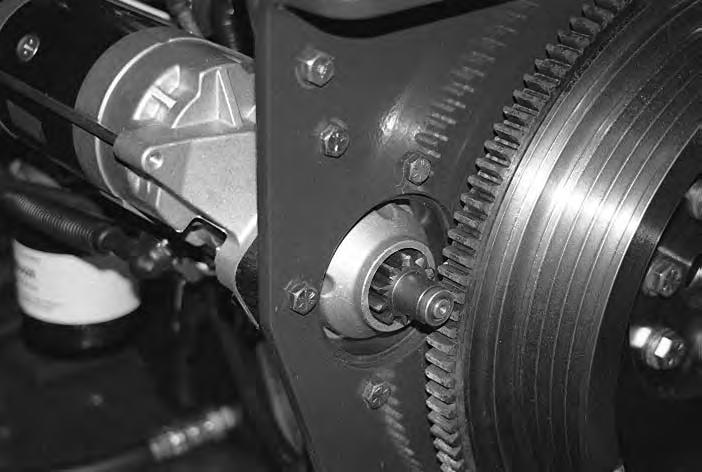
STARTER (S/N 11376 & Above)
Removal and Installation
Open the rear door.
Disconnect the negative (–) cable from the battery.
Remove the flywheel cover (Item 1) [A]
Disconnect the wires and positive (+) cable (Item 1) [B] from the starter solenoid.
Remove the starter mounting bolt (Item 1) [C] and nuts (Item 2) [B]. Disconnect the ground wire from the starter mounting bolt.
Remove the starter.
STARTER (S/N 11376 & Above) (Cont’d)
STARTER (S/N 11376 & Above) (Cont’d)
Disassembly and Assembly
Disconnect the wire from the magnetic switch [A].
Assembly: Tighten the nut to 52–86 in. lbs. (5,9–9,7 Nm) torque. Securely put the rubber boot over the terminal.
Remove the through bolts from the drive end frame [B]
Assembly: Tighten the through bolts to 60–104 in. lbs. (6,8–11,8 Nm) torque.
Remove the field windings housing from the magnetic switch [C]
Assembly: When installing the field windings housing to the magnetic switch, engage the tab (Item 1) [D] on the field windings housing with the notch in the magnetic switch.
STARTER (S/N 11376 & Above) (Cont’d)
Disassembly and Assembly (Cont’d)
Remove the screws from the cover over the brushes.
Remove the cover over the brushes.
Use a long nose pliers, to remove the brushes from the brush holder [A].
Remove the brush holder.
Assembly: Install the negative brushes (brush holder side) to the brush holders (not insulated), and the positive brushes to the brush holders (separated from plate with insulator). Make sure that the positive brush wires are not grounded when assembling the brush holder to the field windings, take care not to damage and get oil on the brushes [B].
Positive Brush B
Brush Holder Insulator
Negative Brush
Remove the armature from the field windings [C]
NOTE:Use a plastic hammer to tap the field windings housing, when necessary to remove the armature.
Positive Brush Holder Hole
Negative Brush Holder Hole
Remove the screws from the drive end frame [D].
Assembly: Tighten the screws to 60–104 in.–lbs. (6,8–11,8 Nm) torque.
STARTER (S/N 11376 & Above) (Cont’d)
Disassembly and Assembly (Cont’d)
Remove the drive end frame from the magnetic switch [A]
Remove the overrunning clutch from the drive endframe [B].
NOTE:If the pinion is installed on the drive end frame (externally attached to the overrunning clutch shaft), it will be necessary to remove the pinion prior to removing the over–running clutch. (See Page 6–23.)
Remove the steel ball from the overrunning clutch [C]
Remove the pinion (Item 1)[D] from the drive end frame.
STARTER (S/N 11376 & Above) (Cont’d)
Disassembly and Assembly (Cont’d)
Remove the retainer and rollers from the drive end frame [A]
Remove the return spring from the magnetic switch [B]
Assembly: Reverse the order of disassembly. Before reassembling, put grease on the following parts:
Overrunning Clutch
Retainer and Rollers
Steel Ball
Return Spring
Armature Bearing
Felt Washer
STARTER (S/N 11376 & Above) (Cont’d)
External Pinion
If the pinion is installed on the drive end frame (externally attached to overrunning clutch shaft), it will be necessary to remove the pinion prior to removing the overrunning clutch.
Push down on the drive end frame [A]
While pressing down on the starter pinion, tap the collar using a pipe (Item 1) [B].
Remove the snap ring (Item 1) [C].
After the snap ring is removed, the pinion, overrunning clutch, shaft, washer, and spring can be removed.
STARTER (S/N 11376 & Above) (Cont’d)
Inspection and Repair
ARMATURE:
Armature Short–Circuit Test: Use a growler tester, put the armature on the growler and hold a hack saw blade against the armature core while slowly rotating the armature [A]. A short circuited armature causes the blade to vibrate and be attracted to the core. An armature which is short–circuited must be replaced.
Armature Winding Ground Test: Use a circuit tester, touch one probe to a commutator segment and the other probe to the armature core [B]. There should be no continuity. If there is continuity, the armature is grounded and must be replaced.
Armature Winding Continuity Test: Use a circuit tester, touch the probes to two commutator segments[C]. There should be continuity at any point. If there is no continuity, the winding is open–circuited, replace the armature.
Commutator Run–Out Test: Check the commutator run–out as shown in [D].
Service Limit – 0.02 inches (0,5 mm)
If the commutator exceeds the service limit, repair as needed.
STARTER (S/N 11376 & Above) (Cont’d)
Inspection and Repair (Cont’d)
ARMATURE (Cont’d)
Measure the commutator outer diameter [A].
Service Limit – 1.38 inches (35 mm)
If it is worn, replace the armature.
Measure the segment mica depth (Item 1) [B]
Service Limit – 0.008 inches (0,2 mm)
If it is worn, undercut the segment mica.
Check the commutator surface for burned spots which usually indicates an open–circuit, and correct it using #400 sand paper.
Check the bearings for wear and damage [C].
If the bearings are worn or damaged, they should be replaced.
Use
STARTER (S/N 11376 & Above) (Cont’d)
Inspection and Repair (Cont’d)
FIELD WINDINGS:
Check the field windings for wear and damage. Check all the connections for clean and tight solderjoints.
Field Winding Ground Test: Use a circuit tester, touch one probe to the field winding end of the brush and the other probe to the surface of the field windings housing [A] There should be no continuity. If there is continuity, the field windings are grounded.
Replace the field windings.
Field Windings Continuity Test: Use a circuit tester, touch one probe to the wire and the other probe to the brush[B] There should be continuity. If there is no continuity, the field windings are open–circuited.
Replace the field windings.
BRUSH AND BRUSH HOLDER:
Measure the brush length.
Service Limit – 0.512 inches (13 mm)
If it exceeds the limit, replace the brush holder or field windings assembly.
Check brush springs, for damage or rust. Replace as needed.
Brush Holder Insulation Test: Use a circuit tester, touch one probe to the positive brush holder plateand the other probe to the holder plate [C]. There should be no continuity. If there is continuity, replace or repair.
OVERRUNNING CLUTCH:
Inspect the pinion, it must rotate freely in the direction of the starter rotation and locked in the opposite rotation[D].
STARTER (S/N 11376 & Above) (Cont’d)
Magnetic Switch Test
The following tests should be done without the armature assembly.
NOTE:Each test should be performed a short time (3 to 5 seconds) to prevent the magnetic switch winding from burning. Each test should be performed with 12 volts.
Pull–In Test: Connect the wires as shown in [A]. When connecting Terminal C and M.T. are closed, the pinion should engage.
Hold–In Test: With the same conditions as in the pull–in test, open the connecting Terminal C [B]. The pinion should remain in the engaged position.
Return Test: With the same conditions as in the hold–in test, open the connecting Terminal 50 [C]. The pinion should return immediately.
M.T.Main Terminal to which the main cable from the battery is connected.
CC–Terminal to which the wire from the field windings is connected.
5050–Terminal to which the wire from the starting switch or stator relay is connected.
No Load Test
The following test should be done after reassembling the starter:
Clamp the starter in a vise. Use a 12 volt battery and ammeter, connect the positive wire of the battery, and the ammeter to the 50 Terminal [D]. Connect the negative wire to the starter body.
The starter should show smooth and steady rotation immediately after the pinion is engaged, it should draw less than the specified current.
Service Limit – 220 Amp. Maximum Draw
Standard Instrument Panel
Removal and Installation
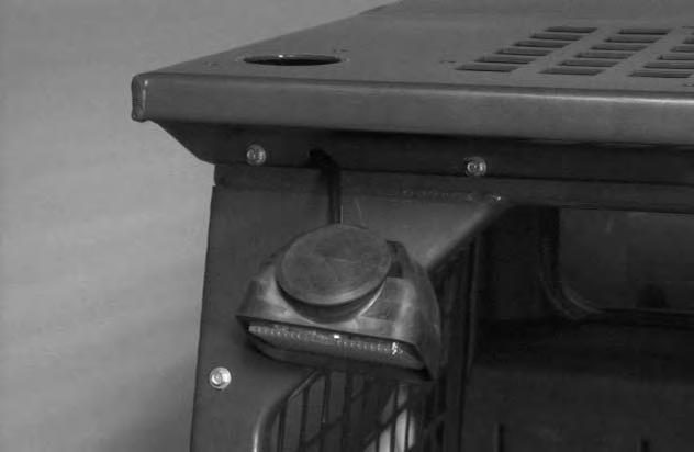
Pry the rubber light mount loose from the operator cab (both sides) [A]
Lower the light from the operator cab and locate the three instrument panel mounting bolts (Item 1)[B] (both sides). Remove the three mounting bolts (Item 1) [B]

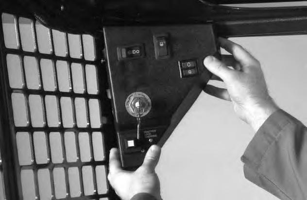

Installation: Be careful not to overtighten the instrument panel mounting bolts to prevent stripping the threaded holes in the panels.
Mark all wires for ease of assembly.
Pull the left instrument panel down and disconnect the wire harness connectors from the panel. Remove the panel [C]
Mark all wires for ease of assembly.
Repeat steps [A] and [B]. Pull the right instrument panel down and disconnect the wire harness connectors from the panel. Remove the panel [D]
Reverse the removal procedure to install the instrument panel.
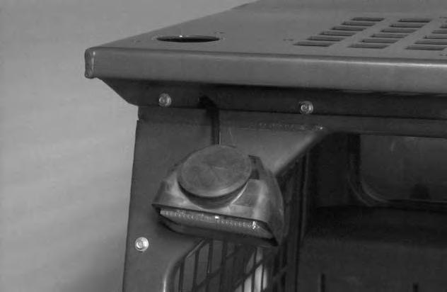
FRONT LIGHTS Removal and Installation
The front lights are mounted in the upper corners of the operator cab [A]
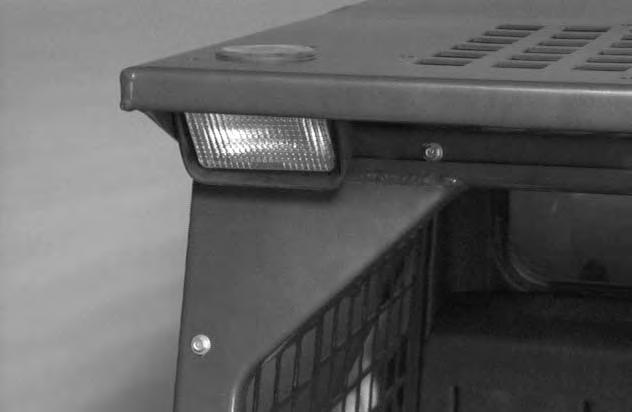
Pull the light down and remove the three mounting bolts (Item 1) [C] from the instrument panel.

Disconnect the front light connector from the instrument panel. Remove the front light from the operator cab.
Reverse the removal procedure to install the front light.
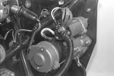
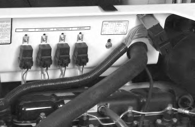
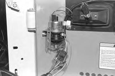
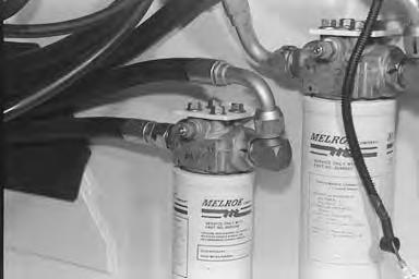
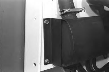
RELAY SWITCHES Location
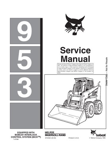
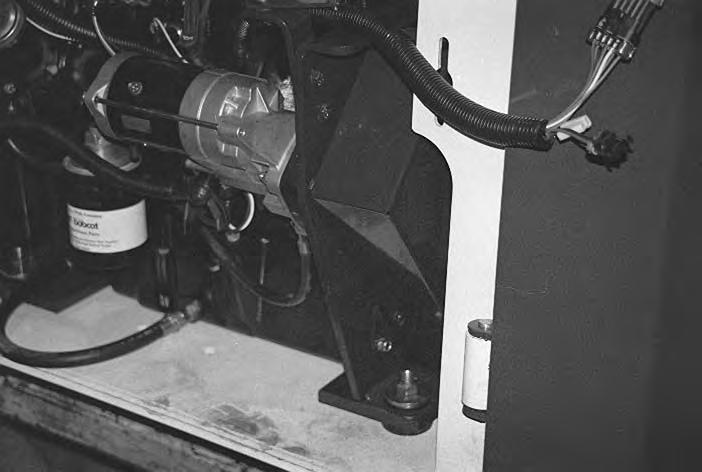
The loader engine harness has relay switches located on the frame above the engine [A]
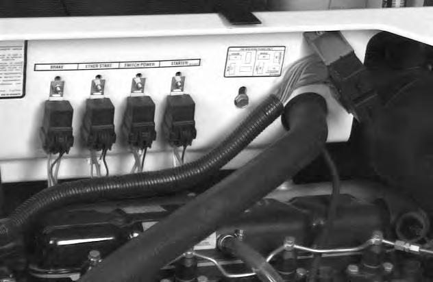
There are four switches (Item 1) [A] on the loader.
The switches are for the starter, switch power, ether start and brake.
Remove the screw from the mounting tab on the switch and replace if the switch malfunctions.
TROUBLESHOOTING Chart
The following troubleshooting chart is provided for assistance in locatingand correcting problems which are most common. Many of the recommended procedures must be done by authorized Bobcat Service Personnel only.
Problem Cause
Key To Correct The Cause
1.Battery capacity low.
2.Bad electrical connections.
3.Faulty starter motor.
4.Incorrect grade of oil.
5.Low cranking speed.
6.Fuel tank empty.
7.Faulty stop control operation.
8.Plugged fuel line.
9.Faulty fuel lift pump.
10.Plugged fuel filter.
11.Restriction in the air cleaner.
12.Air in fuel system.
13.Faulty fuel injection pump.
14.Faulty fuel injectors.
15.Incorrect use of ether start unit.
16.Faulty ether start unit.
17.Broken fuel injection pump drive.
18.Incorrect fuel injection pump timing.
19.Incorrect valve timing.
20Poor compression.
21.Plugged fuel tank vent.
22.Incorrect type or grade of fuel.
23.Exhaust pipe restriction.
24.Cylinder head gasket leaking.
25.Overheating.
26.Cold running.
27.Incorrect tappet adjustment.
28.Sticking valves.
29.Incorrect high pressure fuel pipes.
30.Worn cylinder bores.
31.Worn valves and seats.
32.Broken, worn or sticking piston rings.
33.Worn valve stems or guides.
34.Worn or damaged bearings.
35.Not enough oil in the oil pan.
36.Switch is defective.
37.Oil pump worn.
38.Pressure relief valve is sticking open.
39.Pressure relief valve is sticking closed.
40.Broken relief valve spring.
41.Faulty suction pipe.
42.Plugged oil filter.
43.Piston seizure.
44.Incorrect piston height.
45.Faulty engine mounting.
46.Incorrect alignment of flywheel.
47.Faulty thermostat.
48.Restriction in the water jacket.
49.Loose alternator belt.
50.Plugged radiator.
51.Faulty water pump.
52.Plugged breather pipe.
53.Damaged valve stem oil deflectors.
54.Coolant level to low.
55.Plugged oil pump pipe strainer.
56.Broken valve spring.
VALVE CLEARANCE Adjustment
Make the valve clearance adjustment with engine stopped and cold.
Put the correct size feeler gauge between the rocker arm and the valve stem and turn the adjustment bolt until the clearance is correct [A]
The correct clearance is 0.012’’ (0,30 mm) with theengine cold [B]
Use the following sequence to set the valves: a.With the rocker arm rocking on No. 4, set clearance at No. 1 valves. b.With the rocker arm rocking on No. 2, set clearance at No. 3 valves. c.With the rocker arm rocking on No. 1, set clearance at No. 4 valves. d.With the rocker arm rocking on No. 3, set clearance at No. 2 valves.
0.012 in. (0,30 mm) cold
ENGINE COMPRESSION Checking
The tools listed will be needed to do the following procedure:
MEL10630 – Engine Compression Kit
The engine must be at operating temperature.
Remove the fuel injectors. (See Page 7–14 for the correct procedure.)
Install the correct compression adapter into the engine [A].
Connect the compression gauge [B].
The engine must be turning at about 300–350 RPM. The compression must be between 300–500 PSI (2069–3448 kPa) with no more than 50 PSI (345 kPa) difference between cylinders.
A
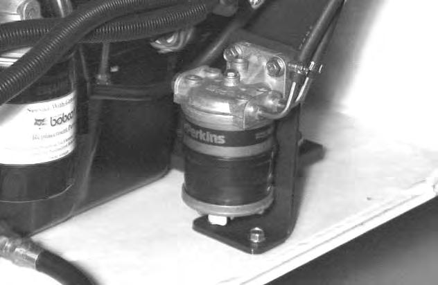
FUEL FILTER Removal and Installation
Replace the fuel filter element every 250 hours of loader operation. Remove the water from the trap ever 8–10 hours.
Clean the area around the filter.
Drain the filter at the drain plug at the bottom of the filter.
Remove the bolt at the top of the filter housing (Item 1)[A] or (Item 1) [D].
S/N 513111559 & Below
S/N 513115072 & Below
Remove the bottom housing from the filter (Item 1)[B] or (Item 2) [D]
Remove the fuel filter element (Item 2)[B] or (Item 3) [D]


Installation: Lubricate the new O–rings before installing them.
Remove the air from the fuel system. (See Page 7–8.)
S/N 513111559 & Below
S/N 513115072 & Below
S/N 513111560 & Above
S/N 513115073 & Above
Fuel Lift Pump
Checking
Install a gauge to the outlet side of the lift pump. Turn the engine for 10 seconds.

STANDARD PRESSURE – 6 PSI (41 kPa)
MINIMUM PRESSURE ACCEPTED – 3.75 PSI (25 kPa).
Removal and Installation
Disconnect fuel in–let hose (Item 1)[A] from the lift pump.
Disconnect the fuel tubeline (Item 1) [B] going to the fuel filter.
Remove the four nuts (Item 1) [C] which fasten the fuel lift pump to the engine.
Remove the lift pump.
Removing Air From Fuel System

Procedure
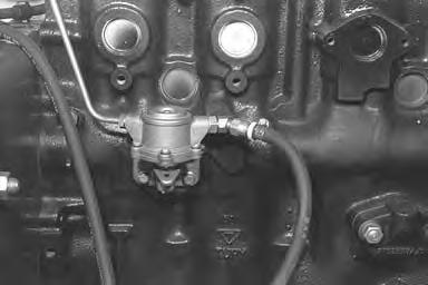
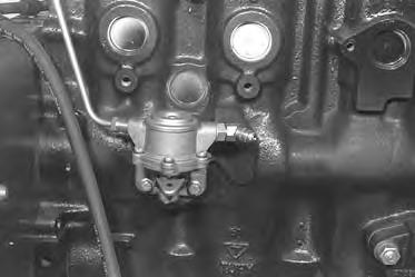
Loosen the plug at the top (Item 1) [A] and the side (Item 2) [A] at the fuel injection pump.
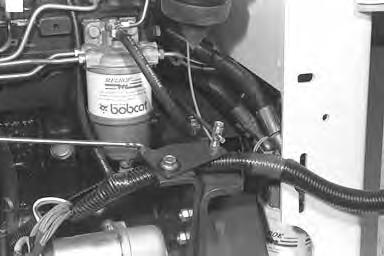
Loosen the bolt at the top of the fuel filter (Item 1) [B]
Operate the fuel lift pump lever pushing fuel and air through the vent plugs.
NOTE:If the lift pump will not pump fuel, rotate the engine a small amount.
When all the air is removed from the fuel system, close the vents in the following order: a.Final fuel filter (Item 1) [B] b.Injection pump side plug (Item 2) [A] c.Injection pump top plug (Item 1) [A]
Loosen all the fittings at the fuel injectors high pressure tubelines (Item 1) [C].
Move the throttle to half open position. Turn the engine with the starter until fuel shows at the fittings. Tighten the fittings to 15 ft.–lbs. (20 Nm) torque.
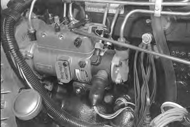
Fuel Injection Pump
The injection pump contains parts which have a very close tolerance and its operations has a direct effect on the performance of the engine.
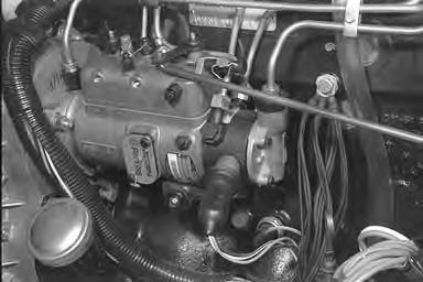

Do not attempt to maintain or adjust unless you are trained and have the correct equipment.
I–2028–0289
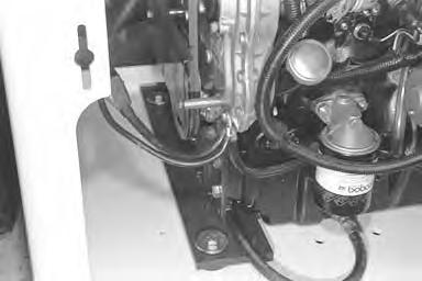
Removal and Installation
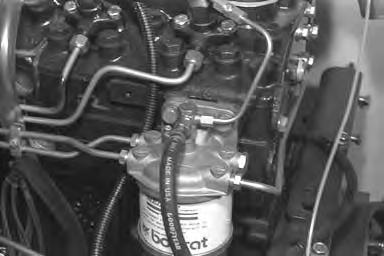
Disconnect the throttle linkage (Item 1) [A]
Disconnect the wires (Item 2) [A] from the fuel shut–off solenoid.
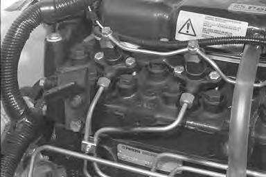
Do not bend the high pressure fuel injection tubes when removing or installing them.


I–2029–0289
Disconnect the high pressure tubelines (Item 1)[B] at the fuel injectors.
Installation: Tighten the high pressure tubeline fittingsto 15 ft.–lbs. (20 Nm) torque when installing them.
Remove all the high pressure tubelines (Item 1)[B] & [C] from the engine.
Disconnect the low pressure tubelines (Item 1) [D] at the fuel filter and injection pump.
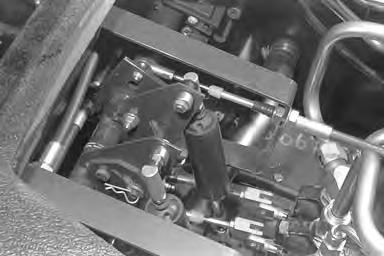
FUEL INJECTION PUMP (Cont’d)

Removal and Installation (Cont’d)
Disconnect the return tubeline (Item 1)[A] at the injection pump.
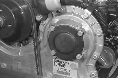
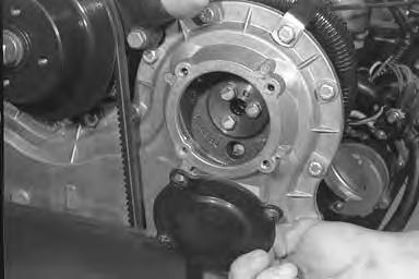
Remove the four bolts (Item 1) [B] at the timing case cover.
Remove the cover [C]
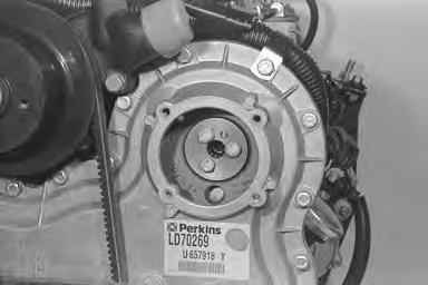
Remove the three bolts (Item 1) [D] from the gear for the injection pump.
Installation: Make sure the injection pump shaft is in correct alignment with the dowel pin.
FUEL INJECTION PUMP (Cont’d)
Removal and Installation (Cont’d)
Remove the nuts and washers [A].
Installation: Before tightening the nuts, make sure the timing marks are in correct alignment.
Remove the injection pump.
Installation: After injection pump is installed the air must be removed from the fuel system. (See Page 7–8 for the correct procedure.)
ENGINE TIMING TO INJECTION PUMP Procedure
The tools listed will be needed to do the following procedure:
MEL1056 – Timing Tool
Remove the valve cover.
Turn the engine until No. 1 cylinder is at TDC, compression stroke (both rocker arms are moving at No. 4 cylinder).
Align the TDC bolt (Item 1) [A] with the mark in the front pulley.
Remove the fuel injection pump. (See Page 7–9.)
ENGINE AND INJECTION PUMP TIMING MARKS
Loosen the screw (Item 1) [B] on the timing tool. Set the correct angle at the gauge according to Injection Pump Code in the chart as listed.
Install the adapter into gear [C]. Make sure the dowel pin is in correct alignment. Install the three bolts and tighten.
Move the plate (with V–notch) over engine mounting flange [D].
Turn the timing tool in opposite direction of engine rotation to remove any gear play.
The engine flange timing mark must be in alignment in the notch on the timing tool plate.
NOTE:If the markers are 180° apart, the No. 1 cylinder is not at TDC.
Checking Timing Mark On Injection Pump Flange
Procedure:
Loosen the screw (Item 1) [A] and install the shaft (Item 2) [A] into the timing tool.
Loosen the screw (Item 3) [A] and turn the plate in the opposite direction.
Loosen the screw (Item 4) [A] and set the gauge to the correct angle according to Injection Pump Code as listed in the chart. (See Page 7–12.)
Locate and mark the No. 1 port at the injection pump. Install the timing tool on the injection pump.
Connect a test pump to the No. 1 port [B]
Operate the test pump until the pressure is at 440 PSI (3033 kPa) maximum.
Turn the tool in the normal rotation of the pump. Whenthe pump reaches the No. 1 port there will be resistance or will not turn.
Move the plate over the mounting flange [C].
NOTE:The mark on the mounting flange is put on at the factory. The mark will almost always be correct. If it is not, you must grind the old mark off and make a new mark.
Diesel fuel or hydraulic fluid under pressure can penetrate skin or eyes causing serious injury. Fluid leaks under pressure may not be visible. Use a piece of cardboard or wood to find leaks. Do not use your bare hand. Wear safety goggles. If fluid enters skin or eyes, get immediate medical attention.
W–2074–1285
Some problems caused by faulty injector nozzles. The engine is hard to start or will not start. Rough engine operation and idle. The engine will not have full power.
The engine exhaust smoke is black, white or blue.
Removal and Installation
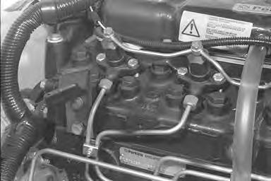
Remove the high pressure tubelines (Item 1) [A].
Do not bend the high pressure fuel injection tubes when removing or installing them.
I–2029–0289
Remove the fuel return tubelines (Item 2) [A].
Remove the nuts from the mounting flange (Item 3) [A]
Installation: Tighten the nuts to 12 ft.–lbs. (16 Nm) torque.
Remove the fuel injector nozzle from the cylinder head [B].
FUEL INJECTOR NOZZLES (Cont’d)
Removal and Installation (Cont’d)
When installing the fuel injector nozzles always replace the copper washer (Item 1)[A] with a new copper washer.
Checking
Do not disassemble or test the fuel injector nozzles unless you have the correct service and testing tools.
The tools listed will be needed to do the following procedure:
MEL10018 – Injection Nozzle Tester
MEL10019 – Accessory Set
Connect the nozzle to a test pump, in adown position [B]
Operate the test pump until the nozzle valve opens:
Setting Pressure – 2572 PSI (17733 kPa)
Working Pressure – 2498 PSI (17223 kPa)
If pressure is not correct, replace or clean nozzle.
Check for inside leakage:
Operate test pump to almost opening pressure. Record pressure, and check pressure decrease for six seconds. The nozzle has a defect if the pressure decreases more than 740 PSI (5162 kPa).
Keep away from fuel under pressure in injector system. It may not be visible. Wear safety goggles. Fuel under pressure can penetrate skin or eyes causing serious injury. If fluid enters skin or eyes, get immediate medical attention.
Checking nozzles spray pattern [C]:
Does not come out the side of the nozzle. Does not have drops coming form nozzle. Does not have a solid stream coming from nozzle.
Any of the above conditions show a defect or dirtyinjector nozzle. Clean or replace any injector nozzle that does not operate correctly.
Engine

Removal and Installation
Raise the lift arms and install the lift arm safety device.
Raise the operator cab. (See Page 1–1.)
Drain the hydraulic reservoir. (See Page 2–1.)
Remove the battery. (See Page 6–1.)
Remove the coolant from the engine and radiator.
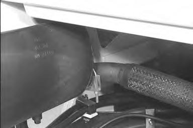
Disconnect the radiator hoses (Item 1) [A] from the engine.
ENGINE (Cont’d)
Removal and Installation (Cont’d)
Disconnect the air cleaner hose fromthe intake manifold. Remove the condition indicator [A]
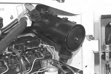
Remove the screws (Item 1) [B] from the air cleaner bands.
Remove the air cleaner and hose from the loader [C]
Disconnect the throttle rod (Item 1) [D] and remove from the loader by removing the set screw (Item 2) [D].
ENGINE (Cont’d)
Removal and Installation (Cont’d)
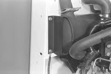
Remove the (4) four engine fuse relays (Item 1) [A] from the chassis by removing the (4) four bolts..
Remove the fuse box (Item 2)[A] by removing the (2) two screws.
Disconnect the engine harness connector (Item 1) [B] from the operator cab harness by removing the bolt.

Remove the harness clamp (Item 2) [B] and remove engine harness from the clamp.
Disconnect the wires from the engine coolant sensor (Item 1) [C] by removing the nut.
When making repairs on hydrostatic and hydraulic systems, clean the work area before disassembly and keep all parts clean. Always use caps and plugs on hoses, tubelines and ports to keep dirt out. Dirt can quickly damage the system.
ENGINE (Cont’d)
Removal and Installation (Cont’d)
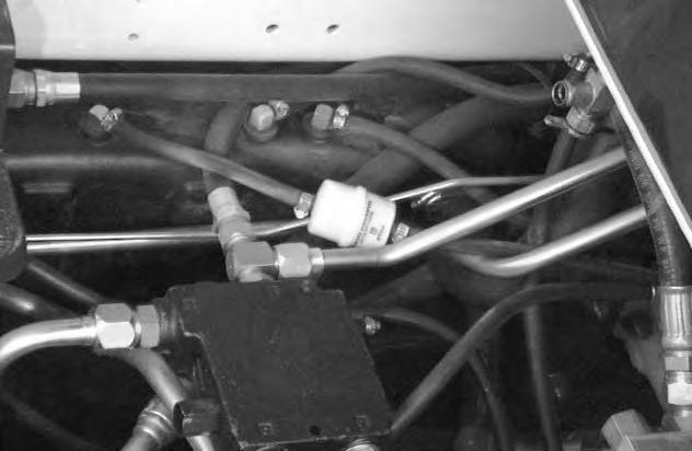
Disconnect the wiring harness from the port block valve [A]
Remove the (3) three bolts (Item 1) [B] at the exhaust manifold and remove the exhaust pipe.
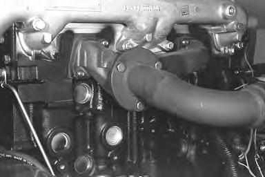

NOTE:When disconnecting any hoses or tubelines, always install caps and plug in the ends.
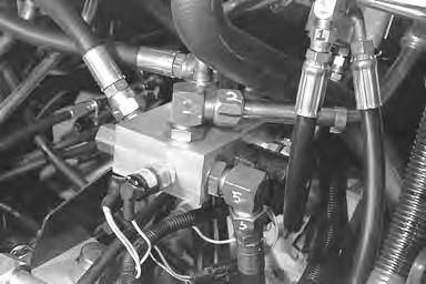
Mark the (4) drive motor hoses (Item 1)[C] for the correct installation.
Disconnect the (4) drive motor hoses (Item 1)[C] from the hydrostatic pump.
Disconnect the motor case drain hose (Item 2) [C] from the hydrostatic pump.
Disconnect the hose (Item 3) [C] from the return filter.
Disconnect the hose (Item 4) [C] going to the hydrostatic filter.
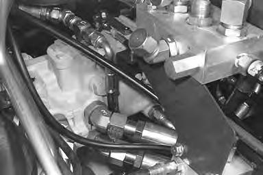
Disconnect the pilot pressure hose (Item 1) [D] to the tilt lock valve, from the fitting on the hydraulic pump.
Disconnect the outlet tube/hose (Item 2) [D] to the main control valve, from the fitting on the hydraulic pump.
Disconnect the hose at the pre–charge port block (Item 3) [D]
Disconnect the hose going to the oil reservoir (Item 4)[D].
Disconnect the hose (Item 5) [D] going to the hydraulic filter.
ENGINE (Cont’d)

Removal and Installation (Cont’d)
ENGINE (Cont’d)
Removal and Installation (Cont’d)
Disconnect the control cables from the control panel [A]
Disconnect the wires connected to the hydraulic and hydrostatic filters [B]
Lower the operator cab.
Disconnect the rear grill gas cylinder. Raise the rear grill all the way up against the operator cab. (See Page 5–1.)
Remove the four mounting bolts at the engine mounts [C]
Installation: Tighten bolts to 125–140 ft.–lbs. (170–190 Nm) torque.
Install a chain into the engine eye hooks [D].
Install a chain hoist.
Lift the engine a small amount. Slide the engine and hydrostatic pump to the rear to givethe engine clearance.

Lift and remove the engine and hydrostatic pump assembly from the loader.
Installation: Reverse the order of removal. Make sure to tighten all hydraulic fittings to prevent leakage.
Radiator And Oil Cooler

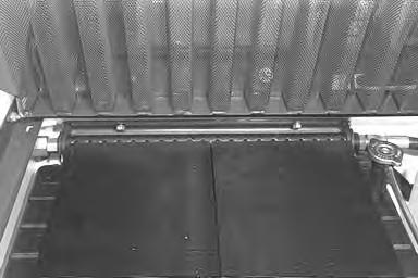
Removal and Installation
Open the rear door. Raise the rear grill. (See Page 5–1.) Remove the radiator cap. Remove the coolant from the engine and radiator. (See Page 7–16.)

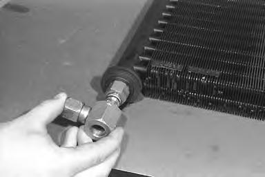
Disconnect both hoses (Item 1) [A] at the oil cooler. Put plugs in the hose ends.
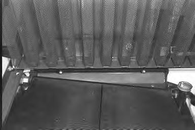
RADIATOR AND OIL COOLER (Cont’d)
Removal and Installation (Cont’d)
Remove the swivel fitting, (Item 1) [A] check the O–rings and back–up washers and replace as needed.
Disconnect the radiator hoses.
Disconnect the wire (Item 1) [B] from the temperature sender switch at the radiator.
Remove the temperature sender switch (Item 2)[B] from the radiator.
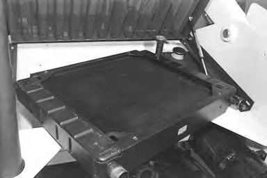
Remove the radiator bolts (Item 1) [C] at the mounting bracket.
Remove the bolts (Item 2)[C] from the frame andremove the bracket (Item 3) [C]
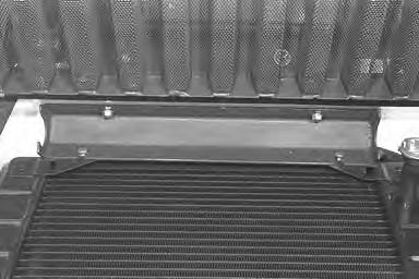
RADIATOR AND OIL COOLER (Cont’d)
Removal and Installation (Cont’d)
Engine Muffler
Removal and Installation
Open the rear door.
Raise the operator cab. (See Page 1–1.)
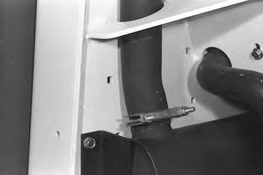
Remove the clamp (Item 1) [A] at the exhaust pipe from the exhaust manifold.
Remove the exhaust pipe from the exhaust manifold by removing the three bolts (Item 1) [B].
Remove the clamp (Item 1) [C]
Remove the three bolts (Item 1) [D]. One bolt is located at the front of the muffler and two at the rear.
Slide the muffler to the rear and remove from the loader.
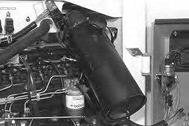
EXHAUST GAS PURIFIER (Optional)
Function
The Exhaust Gas Purifier, when installed on the 943 loader, provides a cleaner exhaust by burning excess carbon particles and gases emitted by the engine.
When the purifier is installed on a new loader, the purifier must be cleaned every 6 to 8 months.
Cleaning the Exhaust Gas Purifier
Remove the purifier from the engine. Use air pressure to force any loose particles or debris from the purifier.
If soft carbon deposits are present, a pressure steam can be used to wash any remaining carbon deposits from the purifier.
NOTE:Do not place the nozzle of the air or steam cleaner inside the purifier. Maximum pressure of 50 PSI (345 kPa) is allowed for the cleaning procedure.
Dry the purifier thoroughly with air.
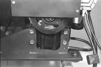
Engine Mounts
Removal and Installation
Remove the engine and hydrostatic pump assembly from the loader. (See Page 7–16.)
Remove the hydrostatic pumps, hydraulic pump and charge pump assembly from the mounts. (See Page 3–1.)
Lift the engine with a chain hoist.
Remove the four bolts (Item 1)[A] at the crankshaft pulley end.
Installation: Tighten the bolts to 125–140 ft.–lbs. (170–190 Nm) torque.
Remove the engine mount.
Remove the flywheel.
Remove the bolts (Item 1) [B] from the mount at the flywheel end.
Remove the engine mount.
Installation: Tighten the bolts to 25–28 ft.–lbs. (34–38 Nm) torque.
Engine Flywheel
Removal and Installation
Remove the bolts (Item 1) [C] from the flywheel.
Remove the flywheel carefully from the crankshaft flange.
Installation: Clean the crankshaft flange of any burrs.
Tighten the bolts to 80 ft.–lbs. (108 Nm) torque.
Flywheel Ring Gear
The ring gear on the flywheel is an interference fit. Heat the ring gear enough to expand it and hit it with a hammer, evenly, to remove it.
Clean the outer surface of the flywheel to give a smooth fit.
Clean the new ring gear and heat it to a temperature of 450–500°F (232–260°C).
Fit the ring gear over the flywheel. Make sure the gear is on its seat correctly.
NOTE:See the Parts Microfiche for Serial Number break if the flywheel is replaced.


Cylinder Head
Removing the Cylinder Head
Clean all the debris from the engine and cylinder head.
Remove the coolant from the engine and radiator. Remove the radiator hoses.
Remove the fuel injectors and fuel tubelines. (See Page 7–14.)
Remove the fuel filter and bracket.
Remove the valve cover.
Remove the nuts from the support brackets of the rocker arms.
Remove the rocker arms.
Loosen and remove the cylinder head bolts.
NOTE:When removing the head, do not use a sharp tool between the head and engine block. Always put the cylinder head on a flat surface such as wood to prevent damage to the machined surface.
Remove the head from the engine block.
Remove the push rods.
See page 7–29 for removing and reconditioning the valves.
Cylinder Head Surface Alignment
Check the surface of the head with a straight edge [A]
The maximum of 0.012’’ (0,305 mm) can be removed from the surface. After milling the head, install a fuel injector nozzle.
The nozzle must not extend more than 0.175’’ beyond the surface. Replace the cylinder head if this dimension is over the limit.
DO NOT add washers under injector nozzles to bring them back into specifications.
I–2080–0995
Installing the Cylinder Head
Install the push rods.
Install a new head gasket. Install it dry, no gasket cement is needed.
When the new head gasket is installed make sure it is positioned correctly over the dowel pinsand the markings Top and Front are located correctly [B]
CYLINDER HEAD (Cont’d)
Installing the Cylinder Head (Cont’d)
Put oil on the threads of the head bolts.
Install the head bolts.
Tighten the bolts in the correct sequence [A]. Do this in a three step procedure to 100 ft.–lbs. (136 Nm) torque.
Example: First tighten all bolts to 30 ft.–lbs. (41 Nm) torque, then 65 ft.–lbs. (88 Nm) torque until the final torque is reached.
NOTE:To reduce the risk of early cylinder head gasket failure, it is recommended that, after a cylinder head has been fitting, the loader be operated at partial load for about 1/2 hour before the cylinder head bolts are torqued again. It is not a good practice just to run the engine without load to make it warm.
Install the rubber seal in the counter–bore of the head for the rocker arm [B]
The lubricating oil connection for the rocker assembly has been changed for engines with a W at the end of the engine number.
If the bolt(s) (Item 1)[C] are to be used again, the threads of the bolt and the threads in the connection must be cleaned and sealant applied.
Use liquid adhesive (LOCTITE) thread seal, apply to the threads under the head of the bolt. The bolt should be tightened to 35 in–lbs. (4,0 Nm) torque.
Install the rocker arms and tighten the nuts.
Adjust the valve clearance. (See Page 7–4.)
Install the valve cover.
Install the fuel injectors and fuel tubelines.
Install the fuel filter and bracket.
Install the radiator hoses.
Add coolant to the engine and radiator.
Valves
Removal of the Valves
Mark the valves so they are put in the original position on assembly [A].
Use a valve spring compressor and remove the valve spring locks [B].
Repeat this procedure for each valve.
Installing the Valves
Make sure the cylinder head is clean.
Put oil on the valve guides and valve stems.
Put each valve in its correct location.
Assemble the valve springs and cups [C].
The intake valve is fitted with a rubber seal.
Use a valve spring compressor and install the valve springs and valve stem locks.
Tap the valve stem with a hammer a small amount to seat the valve stem locks.
Reconditioning the Valves and Valve Seats
Use the correct equipment to grind the valve and valve seat.
The angle of the intake and exhaust valve is 45 °
Check the valve head depth in the cylinder head after grinding [D]. The correct specifications are as follows:
Intake – 0.035/0.045’’ (0,89/1,14 mm)
Exhaust – 0.047/0.057;; (1,19/1,45 mm)
VALVES (Cont’d)
Installing Valve Guides
Check the valve guides for wear with a dial indicator [A] If the movement is more than the listed specification, replace the guide:
Intake – 0.005’’ (0,13 mm)
Exhaust – 0.006’’ (0,15 mm)
NOTE:Make sure to check the valve stem for wear before replacing the valve guide [B].
INT. 0.0015/0.0035’’ (0,038/0,089 mm)
EXH. 0.0225/0.004’’ (0,057/0,10 mm)
INT. 0.3725/0.3735’’ (9,46/9,49 mm)
EXH. 0.375/0.0376’’ (9,53/9,55 mm)
Remove the guide with a hydraulic press or hand operated tool [C]
Remove any metal burrs from the bore in the head before installing the new guide.
0.375/0.376’’ (9,51/9,55 mm)
INT. 4.831/4.847’’ (122,71/123,11 mm)
ESH. 4,847/4.863’’ (123,11/123,52 mm)
Put oil in the bore and press in the new guide [D]
NOTE:Once the guide is started into the bore, donot stop.
Press the guide into the head until it is 0.625’’ (15,87 mm) above the cylinder head.
VALVES (Cont’d)
Installing the Valve Seats
Before replacing the valve seats, install new valve guides. Using the valve guide bore as pilot, machine the recess into the cylinder head as the dimensions show [A].
Make sure to make the correct reference to the intake or exhaust valve seats.
INTAKE
A – 0.283/0.288’’ (7,19/7,31 mm)
B –2.0165/2.0175 (51,22/51,24 mm)
C –Radius 0.015’’ (0,38 mm) Max.
EXHAUST A –0.375/0.380’’ (9,52/9,65 mm)
B – 1.678/1.679’’ (42,62/42,64 mm)
C –Radius 0.015’’ (0,38 mm) Max.
B–2626
Clean the grit from the insert groove.
Use the correct insert tool [B]. Press the insert into the head until it is all the way in and is even with the bottom of the groove.
NOTE:Do not use a hammer to hit the insert for installation.
Grind the new insert as the dimension show [C]
NOTE:Make sure the valve seat is at a included angle of 90 ° so the valve head depth below the head surface is within 0.042/0.052’’ (1,07/1,32 mm)
If the cylinder head surface has been machined, do the following:
Machine the insert groove.
Machine the back of the insert to remove material to give an even fit. Make sure to chamfer the insert to 0.020/0.030’’ (0,508/0,762 mm) at 45 °
Checking the Valve Springs
The valve springs for the intake and exhaust are the same. Check the spring ends for damage and check the specifications [D]
Showing
Rocker Arms
Disassembly
Mark the rocker arms and support brackets for correct assembly.
Remove the snap rings (Item 1) [A] from each end of the shaft (Item 2) [A].
Remove the rocker (Item 3) [A], bracket (Item 4) [A] and spring (Item 5) [A]
Inspect the rocker arm bushings and shaft for wear [B]
Replace the parts as needed.
When installing new bushings in the rocker arms, make sure the oil holes are in alignment [C]
Reverse the order of disassembly and make sure that each set of rocker arm pair has the correct off–set.
Put oil on all the parts for protection.
Piston And Connecting Rods
Removal
Remove the cylinder head. (See Page 7–27.)
Remove the oil pan and balance unit.
Remove the ridge and carbon deposits at the top of the cylinder bore with a ridge reamer.
Make sure the pistons have identification marks [A]
Rotate the crankshaft until a pair of connecting rods are at bottom dead center. Make sure the cap and rod have identification marks [B].
Remove the nuts and remove the bearing cap [C]
NOTE:If the bearings are to be used again, they must be identified so they are returned to their original location.
Using a hammer handle, push the piston and rod out of the block [D].
After the pair has been removed, rotate the engine crankshaft and remove the other pair of pistons.
PISTON AND CONNECTING RODS (Cont’d)
Disassembly
Remove the rings from the pistons. Remove the piston pin.
NOTE:If the piston pin does not come out easily, do not drive it out. Warm the piston in clean oil to a temperature of 120°F (50°C) and push the pin out.
Inspection
Clean all the parts in clean solvent.
Check the clearance of the new rings in the piston grooves [A]
Check the ring gap in the cylinder [B]
Make sure the specifications are correct [C]
Check the piston and pin bushing [D]
Replace the bushings with a hydraulic press. Removeall metal burrs from the piston bore before installing the new bushing.
Use the correct size reamer to fit the new bushing to the piston pin.
PISTON AND CONNECTING RODS (Cont’d)
Inspection (Cont’d)
Check the connecting rod alignment [A]
Installation
Install the piston pin by putting the piston in clean oil at a temperature of 120°F (50°C).
Make sure the identification marks are located correctly at the rod and piston.
Install a new snap ring on each side of the piston pin.
Install the piston rings using an expanding tool to prevent the ring from breaking [B]
NOTE:When fitting internally stepped compression rings, make sure that the step is toward the piston crown [C].
Put oil on the rings so they move freely in the piston grooves.
Position the ring gaps un–evenly around the piston.
NOTE:Before the pistons are installed, check the cylinder bores.
Rotate the crankshaft until a pair of crank pins are at bottom dead center.
Using a ring compression tool, compress the rings on the piston. Make sure the F is to the front of the engine block and install the piston into the block [D]
PISTON AND CONNECTING RODS (Cont’d)
Inspection (Cont’d)
Put oil on the bearings. Install the bearing cap [A].
Tighten the nuts on the connecting rod [B]
Rotate the crankshaft to put the other pair of crank pins at bottom dead center. Repeat the procedure and install the other pair of pistons.
Cylinder Liners
The cylinders are of cast alloy iron and are interference fit to the block.
Check the cylinder bore with an inside micrometer. Check the bore in three positions (top, center & bottom). The checks must be made at parallel and right angles to the center line of the bore, giving six dimensions for each bore.
The standard bore is 3.877/3.879’’ (98,48/98,50 mm).
When the bore is 0.008’’ (0,2 mm) over standard the liner can be bored to 0.030’’ (0,76 mm) oversize. If the bore wear is over 0.030’’ (0,76 mm) replace the liner.
Removal
Remove all the parts from the engine.
Press the cylinder liners out from the bottom of the engine block.
Installation
Clean the bore and remove any metal burrs.
Clean the grease from the liner and dry it.
Put (LOCTITE #242) liquid adhesive 1’’ (25,4 mm) below the upper part of the cylinder block bore.
Push the liner in until 0.030/0.035’’ (0,76/0,89 mm) of the liner is above the block face [A]. Shims can be used to give the correct dimensions.
Bore and hone the liners to the correct dimensions: Std. – 3.877/3.879’’ (98,48/98,50 mm)
NOTE:When using a boring bar on the top face of the engine block, install a parallel plate between the boring bar and engine face.
Main Bearing
The crankshaft has five main bearings. The end play is controlled by a thrust washer on both sides of the center main bearing.
Each main bearing cap has identification marks in relation to the engine block [A]
The position of each cap can not be changed from the original location.
Removal
Remove the oil pan.
Remove the oil pump and balance unit.
Remove the bolts from the main bearing caps.
Remove the main bearing cap and remove the bearing from the cap half.
Remove the top half of the bearing by pushing on one side of the bearing half and rotating the crankshaft [B]
On the center main bearing remove the cap and thrust washers from each side of the cap [C].
Remove the top half of the bearing and thrust washer by pushing on one side of the bearing and rotating the crankshaft [D].
MAIN BEARINGS (Cont’d) Installation
Check the crankshaft journals before installing the main bearings. (See Page 7–38.)
Lubricate the new bearings. Install them by putting the end without the tab into the block and rotating theengine crankshaft until the tab is on its seat.
Install the other bearing half in the main bearing cap. Lubricate the bearing and install it on the engine block. Install the bolts and tighten to position the cap, then loosen them.
Install the center main bearing and thrust washers. Install the center main bearing into the cap. Install the bolts and tighten to position the cap, then loosen them. Repeat the procedure until all the main bearings are installed.
Then tighten the bolts to the correct torque [A].
Crankshaft End Play
The end play can be checked by either a feeler gauge[B] or a dial indicator [C]
The maximum end play is 0.014’’ (0,35 mm). The fitting of oversize thrust washers can be used to correct the end play if it is over the specifications.
Crankshaft
Removal
Remove the oil pan.
Remove the oil pump and balance unit.
Remove the crankshaft pulley, timing case cover, timing gears and timing cover. (See Page 7–43.)
Remove the flywheel. (See Page 7–26.)
Remove the rear main seal. (See Page 7–42.)
Remove the nuts and connecting rod caps. (See Page 7–33.)
Remove the bolts and main bearing caps. (See Page 7–38.)
Lift the crankshaft out of the engine block for inspection.
Checking
Using a micrometer, check the crankshaft for the correct dimensions [A].
NOTE:You can grind the crankshaft to 0.010’’ (0,25 mm), 0.020’’ (0,51 mm) and 0.030’’ (0,76 mm) undersize. (See Page 8–1 for the correct specifications.)
CRANKSHAFT (Cont’d)
Installation
Clean the crankshaft and check that all the oil passages are clean and open.
Clean the engine block, lubricate and install the upper halves of the main bearings.
NOTE:If you do not install new bearings, always return the old bearings back to their original position.
Put the crankshaft, carefully in position.
Install the main bearing and caps. (See Page 7–39.)
Check the crankshaft so that it rotates freely. Check the crankshaft end play. (See Page 7–39.)
Install the rear oil seal.
Install the rear main bride [A]. The rear face of the bridge must be flushed with the rear face of the engine block.
Lubricate the connecting rod bearings. Install the bearings and connecting rod caps. (See Page 7–36.)
Install the oil pump and balance unit.
Install the oil pan.
Install the timing case, timing gears, timing case cover and crankshaft pulley. (See Page 7–43.)
Install the flywheel. (See Page 7–26.)