38 minute read
TROUBLESHOOTING Chart


The following troubleshooting chart is provided for assistance in locating and correcting problems which are most common. Many of the recommended procedures must be done by authorized Bobcat Service Personnel only. W–2004–1285
Problem
No drive on one side, in one direction.
No drive on one side in either directions.
Check for correct function after adjustments, repairs or service. Failure to make correct repairs or adjustments can cause injury or death.
Cause
1, 2, 3
2, 3, 5, 6, 20, 22
The loader does not move in a straight line. 2, 3, 4, 6, 7, 8, 20
The hydrostatic system is overheating. 9, 10, 11, 12, 13, 14, 17, 18, 19
The oil light comes ON. 11, 14, 15, 16, 21
Key To Correct The Cause
1.The hydrostatic system has a fluid leak.
2.The steering linkage needs adjustment.
3.The high pressure replenishing valve(s) are defective.
4.The hydrostatic pumps have a defect.
5.The final drive chain is broken.
6.The hydrostatic motor has a defect.
7.The tires do not have the correct tire pressure.
8.The tires are not the same size.
9.The hydrostatic fluid is not at the correct level.
10.The oil cooler has a restriction.
11.The temperature switch is not operating correctly.
12.The control valve is not operating correctly.
13.The loader is not being operated at the correct RPM.
14.The temperature switches have a defect.
15.There is low charge pressure.
16.Filters need replacing.
17.Fan motor by–pass valve has a defect.
18.Fan motor solenoid valve has a defect.
19.Oil cooler by–pass valve has a defect.
20.Tow valves maybe open.
21.Fluid is too hot.
22.Control sleeve orifice is plugged at hydrostatic pumps.
Lift And Tilt Pedals
Removal and Installation
Remove the control panel from the loader. (See Page 3–39.)
Remove the nut at the cable linkage [A].
Remove the mounting nuts and bolts thatare beneath the pedal [B].
Remove the pedal assembly from the control center [B].
LIFT AND TILT PEDALS (Cont’d)
Removal and Installation (Cont’d)
Remove the nut (Item 1) [A] at the cable end.
Remove the bushing and bolt [B]. Replace the parts as needed.


Pedal Cable Control Linkage
Loosen the small adjusting nut (Item 1) [C] at the cable.
Loosen the large adjusting nuts (Item 1) [D] at the cable.
Disconnect the other end of the cable linkage.
Turn the cable assembly until the large adjusting nuts come off the threads. Remove the cable from the control center.
LIFT AND TILT PEDALS (Cont’d)
Pedal Lock Linkage
Remove the large nut (Item1) [A] (top and bottom).
Remove the two washers and bolt [B]

Replace the parts as needed.
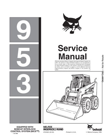
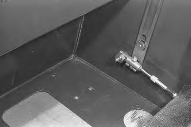
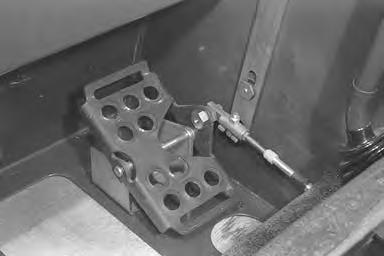
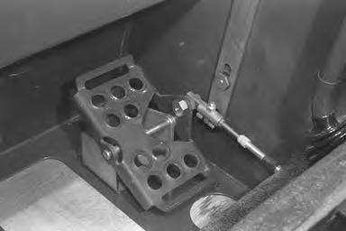
Adjustment
Adjust cable linkage to match the slot in the pedal lock links [A]. This adjustment is necessary for the seat bar system to lock the lift and tilt control pedals when the seat bar is raised. Adjust the pedal bracket for operator control.
Avoid Injury Or Death
The seat bar system must lock the lift and tilt control pedals in neutral when the seat bar is up. Service the system if pedals do not lock correctly.
W–2105–1285

Steering Levers And Shaft

Removal and Installation
Remove the pedal control panel. (See Page 3–4.)
Remove the nuts and bolts (Item 1) [A] (top and bottom) which fasten the cable mounting brackets.
Disconnect the auxiliiary cable linkage (Item 1) [B] (both sides).
Installation: Adjust the steering levers at the dimension shown. Adjust so that they are both even [C]. See Page 3–30 for the complete neutral adjustment procedure.
Disconnect the auxiliary cable linkage (both sides) [D].
Remove the spring adjustment bolts (Item 1) [D] (both sides).
Installation: Adjust the tube stop plate to hold the levers in the neutral position [D]
NOTE:The plate has a slot for one tube stop, adjust this tube stops so there is no play between the spring ends & tube stops.

STEERING LEVERS AND SHAFT (Cont’d)
Removal and Installation (Cont’d)
Remove the bottom pivot bolt (Item 1) [A] for the steering lever.
Remove the top pivot bolt (Item 2) [A] for the steering levers.
Installation: Use LOCTITE on the bolts and nuts when assembling the steering levers.
Remove the top and bottom plastic bushings [B]
Remove the steering shaft bolt (Item 1) [C] (both sides).
STEERING LEVERS AND SHAFT (Cont’d)
Removal and Installation (Cont’d)
Remove the steering shaft assembly. Using a locking pliers, disengage the spring (both sides) [A]

Remove the bushings (Item 1)[B], spring (Item 2)[B] and the plastic washer (Item 3) [B]
Remove
STEERING LEVERS AND SHAFT (Cont’d)
Removal and Installation (Cont’d)
Remove the steering pivot shaft from the center shaft[A]. Replace the center plastic bushings and wave washer as needed [A]

If the steering levers are to be removeduse the following procedure:

Remove the hand grip by plugging the hole at the bottom of the steering lever and use air pressure to remove the grip [B]
Remove the steering lever from the control center [C]
HYDROSTATIC MOTOR Removal and Installation
When making repairs on hydrostatic and hydraulic systems, clean the work area before disassembly and keep all parts clean. Always use caps and plugs on hoses, tubelines and ports to keep dirt out. Dirt can quickly damage the system.
The tool listed will be needed for the following procedure: MEL1244 – Crowfoot Wrench
Lift and block the loader. (See Page 1–1.)
Raise the lift arms and have a second person install a lift arm support device. (See Page 1–1.)
Stop the engine. Raise the operator cab.(See Page 1–1.)
Remove the control panel. (See Page 3–40.)
Remove the front tire on the side that the motor is to be removed.
Remove the motor access cover.
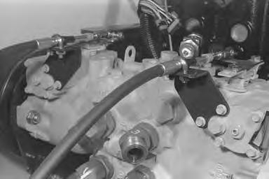
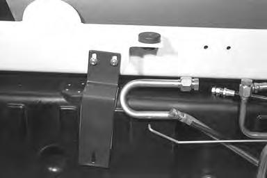
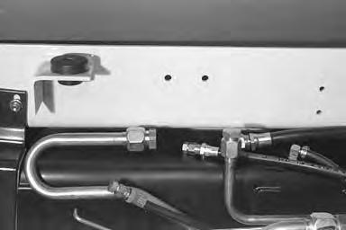
Disconnect the case drain hose (Item 1) [A]
S/N 513111560 & Above; S/N 513115073 & Above Only: Disconnect the case flushing hose (Item 1) [B].
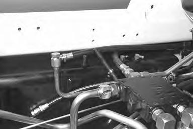
Disconnect the high pressure hoses (Items 1 & 2) [C]
Remove the mounting bolts [C]
Installation: Tighten the bolts to 110–120 ft.–lbs. (149–163 Nm) torque.

Identify the top and bottom of the motor and mark it before removal. Motors can be installed for rotation in either direction. Incorrect installation will reverse the action of the loader controls.


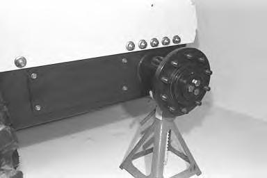
Slide the motor out of the gearcase. Turn the motor side ways and remove it from the loader [D]
Installation: Fill the motor case 3/4 to 7/8 full of clean oil through the case drain hole.
HYDROSTATIC MOTOR (Cont’d)
Disassembly and Assembly
Remove the four bolts [A]
Installation: Tighten the four bolts to 51–62 ft.–lbs. 69–84 Nm) torque.
Remove the end cap [B].
Remove the gasket [C].
Remove the wafer plate [D]
Installation: Make sure the dowel pin goesinto the notch in the wafer plate. The wafer plate centers on the bearing which extends from the housing about 0.150’’ (3,81 mm).
HYDROSTATIC MOTOR (Cont’d)
Disassembly and Assembly (Cont’d)
Remove the rotating group assembly [A].
Remove the wear plate [B].
Remove the first snap ring [C].
Using a seal puller, remove the seal from the housing.
Remove the second snap ring [C]
Remove the shaft and bearing assembly [D]
HYDROSTATIC MOTOR (Cont’d)
Inspection:
Before the hydrostatic motor is assembled, check the following items: a.Wafer plate. b.Rotating group pistons. c.Piston shoes. d.Wear plate. e.Shaft bearing and splines.
Check all the contact surfaces. Replace any parts that have scratches or are worn that can cause leakage. Clean all the parts in solvent and use air pressure to dry the parts. Do Not use cloth or paper because small pieces of material can get into the hydrostatic system. Do Not use sandpaper or a file to remove scratches on any of the parts.
NOTE:Always use new gaskets and seals when assembling the motor.
Install a new seal using the correct size seal driver tool [A]
NOTE:Later production hydrostatic motors (Model #46–3013) have a pump style cylinder block, where early production motors (Model #46–3014) had a motor style cylinder block [B] & [C].
Hydrostatic Pump
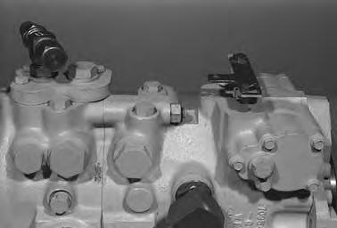
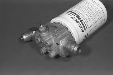
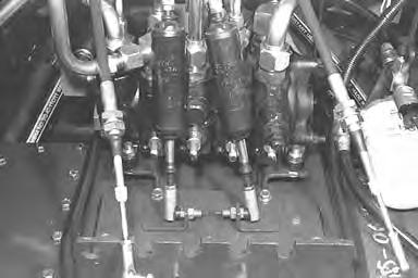
High Pressure and Replenishing Valves
When making repairs on hydrostatic and hydraulic systems, clean the work area before disassembly and keep all parts clean. Always use caps and plugs on hoses, tubelines and ports to keep dirt out. Dirt can quickly damage the system.
The high pressure relief replenishing valves are located on the inside and outside of the pump [A] & [B].
The functions of the high pressure replenishing relief valves are as follows:

1.Give replacement fluid to the low pressure side of the hydrostatic circuit. Replacement fluid is needed because of the normal inside leakage and the controlled flow for cooling.
2.To keep the high pressure flow of the fluid out of the low pressure side of the circuit.

3.Release very high pressure caused by a high overload when traveling in a forward or reverse direction.
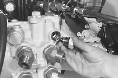
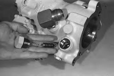
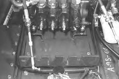
Checking the High Pressure Relief Replenishing Valve
If there is a loss of drive in one direction, on one side of the loader, use the following procedure to check the high pressure relief valves:
Lift and block the loader. (See Page 1–1.)
Raise the operator cab. (See Page 1–1.)
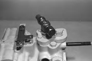
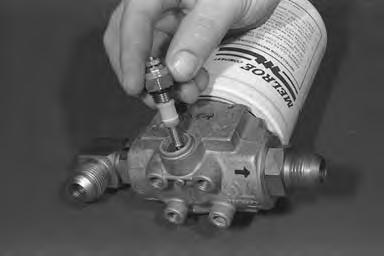
Remove the high pressure relief valve from top and bottom ports and switch them around [A] & [B]
If the loss of the drive goes to the other side of the loader, the valve which controls that side of the loader must be replaced.
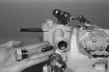
Checking Charge Relief Pressure
Remove the charge pressure switch.
Connect a gauge to the port [C].
The pressure must be approximately 400 PSI (2758 kPa) cold fluid.
If not, remove the charge relief valve and add or remove shims until the pressure is correct [D]
NOTE:Do not add more than 0.350 inch (8,9 mm) thickness of shims.
HYDROSTATIC PUMP (Cont’d) Removal and Installation
When making repairs on hydrostatic and hydraulic systems, clean the work area before disassembly and keep all parts clean. Always use caps and plugs on hoses, tubelines and ports to keep dirt out. Dirt can quickly damage the system.
I–2003–0284
Lift and block the loader. (See Page 1–1.)
Raise the lift arms and have a second person install a lift arm support devise. (See Page 1–1.)
Remove the engine and hydrostatic pump as an assembly from the loader. (See Page 7–1.)
Put the engine and hydrostatic pumps on a work bench.
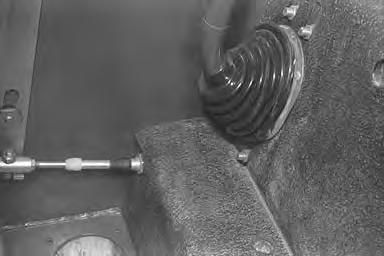
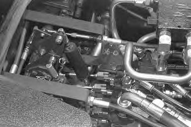
Disconnect the steering cables (Item 1) [A] at the pump control levers.

HYDROSTATIC PUMP (Cont’d)

Removal and Installation (Cont’d)
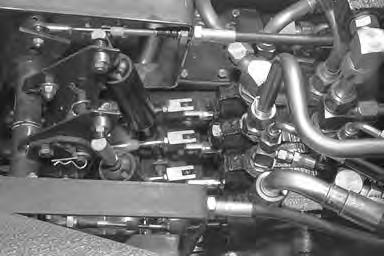
Remove the bolts for the steering cable mounting brackets (Item 1) [A]
Remove the steering cables and mounting bracket assembly (Item 1) [B].
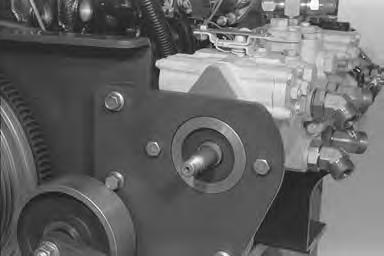
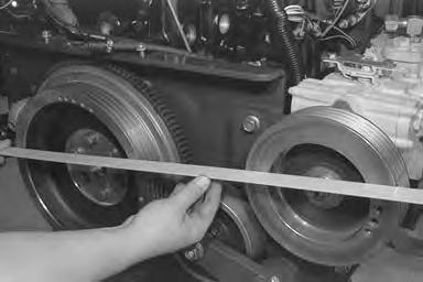
Remove the drive belt. (See Page 3–1.)
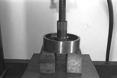
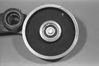
Loosen the nut at the pulley.
Installation: Tighten the nut to 175–200 ft.–lbs. (237–271 Nm) torque.
Use a port–a–power to remove the pulley [C]

HYDROSTATIC PUMP (Cont’d)
Removal and Installation (Cont’d)
Loosen the bolts and nuts (Item 1) [A] at the pump mounting brackets.
Installation: Tighten the bolts and nuts to 65–70 ft.–lbs. (88–95 Nm) torque.
Put a chain around the hydrostatic pump assembly. Attach a chain hoist, remove the mounting bolts and lift the pump from the mounting brackets [B]

Put the hydrostatic pump assembly on a work bench.
Remove the charge pump and hydraulic pump from the hydrostatic pumps.
Installation: Make sure to make alignment of the engine flywheel and hydrostatic pump pulley. Use a straight edge, with no gap at either the pulley or flywheel[C]. After the alignment is correct, tighten the bolts and nuts at the mounting brackets for the hydrostatic pump (both sides). Tighten to 65–70 ft.–lbs. (88–95 Nm) torque.
HYDROSTATIC PUMP (Cont’d) Disassembly and Assembly


When making repairs on hydrostatic and hydraulic systems, clean the work area before disassembly and keep all parts clean. Always use caps and plugs on hoses, tubelines and ports to keep dirt out. Dirt can quickly damage the system.
NOTE:Keep the front and rear pump parts separate during disassembly and assembly.
Remove the two bolts (Item 1) [A]. One bolt is located on each side.
Remove the nut (Item 1) [B] from the stud.
Separate the two pumps. Remove the O–ring (Item 1) [C], splined coupler (Item 2) [C] and alignment spacer (Item 3) [C]
HYDROSTATIC PUMP (Cont’d)
Disassembly and Assembly (Cont’d)
Both Pumps:
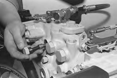
Remove the replenishing poppet, spring and plug [A].
Both Pumps:
Remove the high pressure relief valve, spring, shims and plug [B]

Front Pump:
Remove the charge relief poppet, spring and plug [C].
NOTE:Do not use more than 0.220’’ (5,6 mm) shims behind the spring when adjusting the charge pressure.
Front Pump:
Remove the bolts (Item 1) [D] at the charge manifold block.
HYDROSTATIC PUMP (Cont’d)
Disassembly and Assembly (Cont’d)
Front Pump:
Remove the charge manifold block and O–rings [A].
Remove the plug at the charge orifice port.
Use an allen wrench, loosen the charge orifice [B]. Remove the orifice from the port [B]
Both Pumps:
Mark the position of the neutral for a reference when assembling the pumps [C]
This adjustment will be finished when the pumps are installed and engine running for neutral position. (See Page 3–1.)
Remove the bolt. Remove the spool controland lever [C].
Both Pumps:
Using pliers, remove the sleeve control [D]
HYDROSTATIC PUMP (Cont’d)
Disassembly and Assembly (Cont’d)
Both Pumps:
Remove the end housing bolts [A].
Installation: Tighten the bolts to the correct torque as follows:
3/8’’ Bolts – 39–47 ft.–lbs. (53–64 Nm)
7/16’’ Bolts – 60–74 ft.–lbs. (81–100 Nm)
Both Pumps:
Lift the end housing and shaft from the pump body [B].
Both Pumps: Remove the Teflon plastic guides for the swashplate cradle [C]
Rear Pump: Remove the snap ring at the bearing [D]
HYDROSTATIC PUMP (Cont’d)
Disassembly and Assembly (Cont’d)
Rear Pump: Remove the bearing and shaft assembly [A].
Front Pump: Remove the snap ring at the seal [B]
Front Pump: Drill a hole in the seal [C]
Front Pump: Install a seal puller and remove the seal [D]
HYDROSTATIC PUMP (Cont’d)
Disassembly and Assembly (Cont’d)
Front Pump:
Remove the snap ring at the bearing [A].
Front Pump: Remove the bearing and shaft assembly [B].
Both Pumps: Remove the swashplate [C].
Both Pumps: Remove the guide at the side of the swashplate [D]
HYDROSTATIC PUMP (Cont’d)
Disassembly and Assembly (Cont’d)
Both Pumps:
Use a snap ring pliers, remove the rotating group [A]
Both Pumps:
To remove the wear plate, use an O–ring tool and reach into the housing lift one edge of the wear plate [B].
Both Pumps: Remove the wear plate [C].
NOTE:Identify the wafer plate relationship to the pump. The feathering groove must be installed correctly. Mark the plate for correct installation on the R.H. and L.H. pump [C].
Both Pumps:
Remove the end cap and gasket from the swashplate piston [D]
Installation: Tighten the bolts to 100 in.–lbs. (11 Nm) torque.
HYDROSTATIC PUMP (Cont’d)
Disassembly and Assembly (Cont’d)
Both Pumps:
Take a reading between the piston and housing and make a record of it [A]. The approximate space between the piston and end cap is 0.50’’ (12,7 mm).
This will get the mechanical neutral adjustment approximately back to where it was, but the final adjustment will have to be made with the engine running. (See page 3–1.)
Both Pumps:
Remove the bolts at the end cap [B]
Installation: Tighten the bolts to 100 in.–lbs. (11 Nm) torque.
Pull the piston into the housing and remove the seal and O–ring [C]
Remove the piston and end cap assembly from the housing.
Remove the neutral adjustment nut and remove the end cap [D]
Remove the seal and O–ring.
HYDROSTATIC PUMP (Cont’d)
Disassembly and Assembly (Cont’d)
On Later Built Pumps Bearing Ring Was Added:
Assembly: Before installing bearing ring, it must be pre–formed. Bend the bearing ring around your finger until the O.D. is approximately 1.0’’ (25 mm), then slide the bearing ring into a slightly larger than 1.0’’ (25 mm) I.D. tube. Let is stand for 5 minutes.
Install the piston into the bore [A].
Install the bearing rings into the bearing groove, O–rings and piston ring over its O–ring.
DO NOT install the piston ring closest to the neutral adjustment bolt.
Assembly: Push the piston into the bore until the other end comes out just far enough to install the other end bearing ring, O–ring and seal [B].
Push the piston back into the bore and center the piston.
Tighten the nut at the piston to release the spring tension on the snap ring [C]
Assembly: Adjust the nut so there is no freeplay between the spring cap and the nut.
Remove the snap ring [D].
HYDROSTATIC PUMP (Cont’d)
Disassembly and Assembly (Cont’d)
Remove the spring assembly [A].
If the needle bearings in the housing need to be replaced, use the correct size driver tool and remove the bearing [B]
Installation: Turn the housing over and install the bearing from the other side.
Inspection:
Check the drive shaft splines and bearings.
Check the wear plate. The finish must be smooth and free of grooves. If the grooves can be felt with a fingernail, replace the wear plate.
Remove the pistons and shoe assembly [C].
Check each piston shoe for scratches.
Check each piston in its cylinder bore. The piston must move freely.
Check the flat surface of the piston block for being smooth and free of scratches.
Inspect the pins and spherical washer for wear and damage [D].
All the pins must be the same length and not bent.
Check the spherical washer for sharp edges.
NOTE:If there is any defect in the rotating group, the complete unit must be replaced.
HYDROSTATIC PUMP (Cont’d)
Disassembly and Assembly (Cont’d)
The assembly procedure is the reverse order of the disassembly with the exception of the following:
Install the shaft pulley end seal using the correct size seal driver tool [A]
Install the snap ring over the seal.
When installing the spool control and sleeve make sure the notch in the spool and the notch in the sleeve are in alignment [B]
The notches (Item 1) [B] go toward the shaft end of the pump housing and the notch in the sleeve goes over the small dowel pin in the swashplate.
HYDROSTATIC PUMP (Cont’d) Neutral Adjustment
1.Eliminate Wheel Creep
Before you make adjustments, do the following: With the loader on level ground, operator in the loader seat, start the engine. Parking brake disengaged and the steering levers in neutral position and the loader does not creep, go to paragraph 2.
If the loader does creep, lift and block the loader. (See Page 1–1.)
Raise the operator cab. (See Page 1–1.)
Disconnect the steering cables at the hydrostatic pump levers. Start the engine, if the creep has stopped, go the paragraph 2.
If creep is still present, adjust neutral at the hydrostatic pumps as follows: a.Engage the parking brake. Start the engine. b.Loosen the bolt (Item 1) [A] at the displacement control sleeve. c.Turn the displacement control sleeve, with a screwdriver through neutral and mark both positions where there is noise from the transmission (forward and rearward). d.Set the location midway between these positions. Repeat the procedure for the other side. e.Stop the engine. Disengage the parking brake.
NOTE:Make sure to adjust the cable linkage so the ends align with the holes in the levers and the hydrostatic pumps stay in neutral.
2.To Set Steering Lever Neutral Position
Raise the operator cab. (See Page 1–1.)
Disconnect the steering cables at the steering levers. Loosen the nuts at the spring stops (Item 1) [B] & [C]
Loosen the bolt at the steering shaft (Item 2) [C].
HYDROSTATIC PUMP (Cont’d)
Neutral Adjustment (Cont’d)
Position the steering lever so it is vertical (approximately 13.5–14.5’’ [343–368 mm]) ahead of the rear edge of the control module [A]. Make sure both steering levers are even.
Eliminate the free play at the steering lever by positioning the lower spring stop (Item 1) [B] so the spring contacts all the stops simultaneously when the steering lever is in the neutral position.
Adjust the location of the ball joints at the steering cable so the ball joint can be fastened to both the hydrostatic pump and steering lever without stroking either one.
Make sure the steering cable is secured in its mounts. Repeat the procedure for the other side.
3.To Set the End Stroke Stops at the Steering Levers
Loosen the stops (Item 1) [C] and slide them away from the steering lever.
Put a 0.0625’’ (16 mm) spacer (Item 1) [D] between one of the hydrostatic pump levers and its stop.
Move the steering lever forward until the pump lever stops against the spacer. With the steering lever held at this position, slide the lower stop up until it contacts the steering lever and tighten the nuts [C].
Repeat the procedure with the same steering lever moved to the rear and fasten the upper stop.
Repeat the above procedure with the other pump and steering levers.
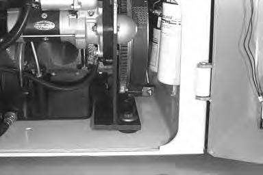
Hydrostatic Filter
Removal and Installation
Raise the operator cab. (See Page 1–1.)
Drain the fluid from the reservoir. (See Page 2–1.)


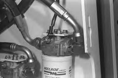
Disconnect the wire from the sending switch [A]
Disconnect the hose [B]
Disconnect the hose [C]
Remove the mounting bolts [D].
Remove the filter housing from the loader.

HYDROSTATIC FILTER (Cont’d)
Disassembly and Assembly
Loosen the pressure switch (Item 1) [A].
Remove the pressure switch [B]
Case Drain Filter
The case drain filter (Item 1) [C] must be replaced whenever there have been major repairs to the hydrostatic pumps or motors.

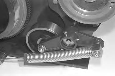
DRIVE BELT Removal and Installation

To replace the drive belt with the engine and hydrostatic pumps installed in the loader use the following procedure:


Remove safety shield by removing 3 bolts.
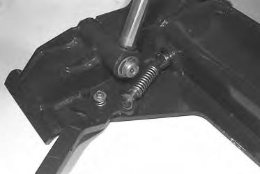
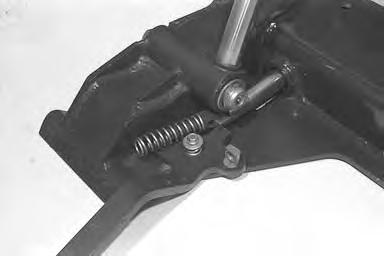
Remove the adjustment nut (Item 1) [A] at the spring.
Turn the large nut (Item 1) [C] until the spring tension is released.
Remove
DRIVE BELT (Cont’d)
Install the new belt.
Adjustment:
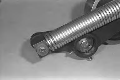
Turn the large nut (Item 1) [A] until the spring is at full tension (until the spring end cap) (Item 2) [A] makes contact with mount (Item 3) [A]
Install and tighten the adjustment nut (Item 4) [A] until there is 0.060–0.120’’ (1,5–3,0 mm) between the adjusting nut (Item 4) [A] and the large nut (Item 1) [A] (approximately 3/4 turn away from the large nut).

Install and tighten the jam nut (Item 5) [A].

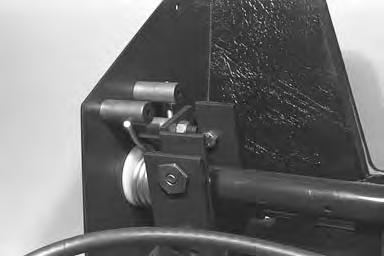
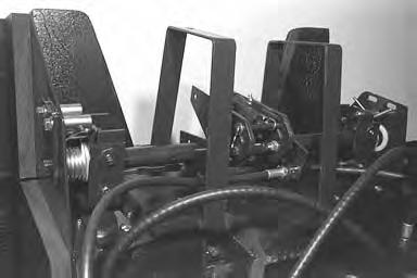
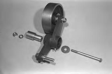
Drive Belt Tension Pulley
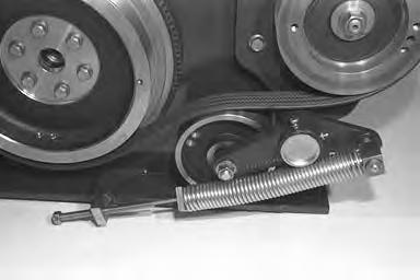

Removal and Installation
NOTE:Engine removed for photo clarity.
Remove the hydraulic and hydrostatic filter elements for clearance.
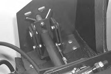
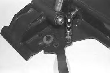
Remove the jam nut (Item 1) [A]
Remove the adjusting nut (Item 2) [A]
Loosen the large nut with threaded rod (Item 1) [B]
Remove the grease cap (Item 2) [B].
Remove the threaded rod (Item 1)[B] from the spring end cap (Item 3) [C]
Remove the bolt at the pulley bracket pivot [D].
Installation: Tighten the bolt to 65–70 ft.–lbs. (88–95 Nm) torque.
Remove the pulley bracket and pivot assemlby.
DRIVE BELT TENSION PULLEY (Cont’d)
Removal and Installation (Cont’d)
Remove the snap ring (Item 1) [A] at the base end of the spring.
Remove the spring assembly.
Remove the bolt (Item 1) [B], washer (Item 2) [B], bushing (Item 3) [B], washer (Item 4) [B] and nut (Item 5) [B].
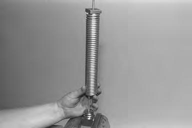
If the spring has to be replaced, use the following procedure:
Put the end cap in a vise [C]
Using a hammer and punch, hit the end of spring until it starts to turn off the end cap [C]
Turn the spring until it comes off the end cap [D]
Repeat this procedure for the other end.
NOTE:DO NOT use a pipe wrench on the spring coils. Any marks put into the spring coils will cause breakage when the spring is at full tension.

DRIVE BELT TENSION PULLEY (Cont’d)
Removal and Installation (Cont’d)
Remove the snap ring (Item 1) [A] and bolt (Item 2) [A] from the pulley.

Installation: Tighten the bolt to 25–28 ft.–lbs. (34–38 Nm) torque.
CONTROL PANEL Removal and Installation
Engage the parking brake. Raise the lift arms and have a second person install a lift arm support device. (See Page 1–1.)
Stop the engine. Raise the operator cab.(See Page 1–1.)
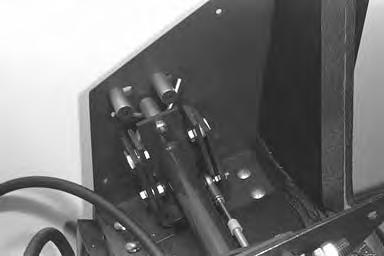
Disconnect both hydraulic shock absorbers (Item 1) [A] at the steering linkage.
Disconnect all the cable linkages (Item 1) [B] at the control valve.
Remove the two bolts which fasten the mounting brackets, for the control valve cables, to the chaincase.

Disconnect the steering cable ends (Item 1) [C] (both sides).
Loosen one of the mounting nuts at the steering cable (Item 2) [C] (both sides).
CONTROL PANEL (Cont’d)
Removal and Installation (Cont’d)
Loosen the bolt (Item 1) [A] at the throttle lever and move forward. Disconnect the throttle linkage.

Remove the lift arm by–pass knob (Item 1)[B] and rubber washer (Item 2) [B]
Remove the screws at the clean–out tubes (both sides) [C]
Using a chain hoist, lift the control center from the loader [D].
Parking Brake
Removal and Installation
Raise the loader operator cab. (See Page 1–1.)
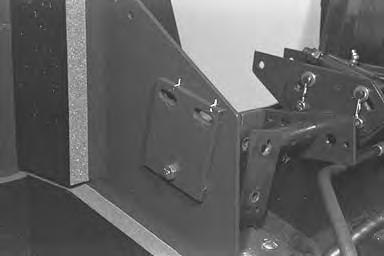
Remove the (2) mounting bolts (Item 1)[A] from the brake pedal mounting bracket.
Installation: Tighten the mounting bolts to 25–28 ft.–lbs. (34–38 Nm) torque.
Disconnect the electrical connector from the parking brake pedal sensor (Item 2)[A]. The connector is located behind the control panel.
Remove the parking brake assembly from the loader by moving the rubber floor mat and removing the tube clamp (Item 1) [C] and sliding the tube and wires out.
Reverse the removal procedure to install the parking brake assembly in the loader.
Disassembly and Assembly
Loosen and remove the mounting bolt (Item 1)[B] and nut from the spring mounting bracket (Item 2) [B].
Remove the brake pedal spring (Item 3) [B] from the tension spring mounting bracket (Item 2)[B] and from the brake pedal mounting bracket (Item 4) [B]
Remove the (2) mounting bolts, washers and nuts (Item 5) [B] from the brake pedal sensor.

Remove the harness mounting clamp (Item 1) [C] from the pedal mounting bracket (Item 4) [B]
Remove the sensor harness form the pedal mounting bracket.
Remove the pedal Mounting bolt (Item 6) [B], plastic spacers and bushing nut from the brake pedal.
Remove the pedal from the pedal mounting bracket.
Parking Brake Disc
Removal and Installation
Raise the lift arms and have a second person install a lift arm support device. (See Page 1–1.)
Raise the operator cab. (See Page 1–1.)
Remove the control panel. (See Page 3–1.)
Drain the fuel tanks. (See Page 5–1.)
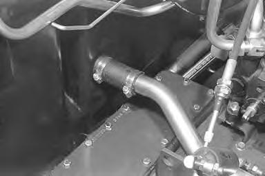
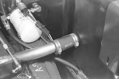
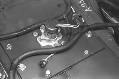
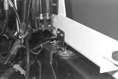
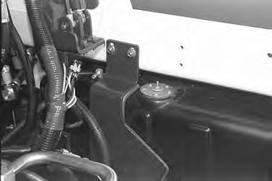
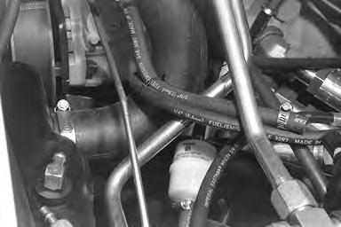
Remove the cross over tube from between the fuel tanks [A] & [B]
Remove the shock bracket assembly (Item 1) [C] by removing the 2 bolts (Item 2) [C].
Remove the cable mount bracket (Item 1) [D] by removing the 2 bolts (Item 2) [D]
PARKING BRAKE DISC (Cont’d)
Removal and Installation (Cont’d)
Remove the bolts from two hose clamps (Item 1) [A].
Disconnect brake harness connector (Item 2) [A].
Remove the remaining bolts and remove the chaincase cover.

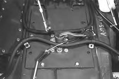
Remove the chaincase cover (Item 1) [B] from the chaincase.
Inspect the brake disc guide (Item 2) [B] for damage or wear and replace as needed.
PARKING BRAKE DISC (Cont’d)
Removal and Installation (Cont’d)
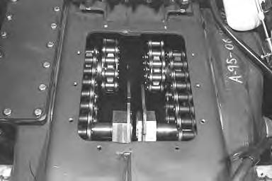
Use a snap ring pliers and move the snap ring (Item 1)[A] toward the gearcase houising.
Move the large nut toward the gearcase housing for clearance to remove the disc brake.
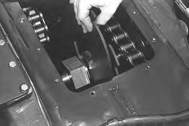
Use a snap ring pliers with 90° tips and remove the snap ring from the end of the large nut on the gearcase shaft

Slide the disc (Item 1)[C] off the large nut and remove the brake disc through the center hole.
Reverse the removal procedure to install the parking brake disc into the loader.

Axle Seal And Wear Ring
Removal and Installation
The tools listed will be needed to do the following procedure:
MEL1242 – Port–a–Power
MEL1255 – Axle Seal Tool
Lift and block the loader. (See Page 1–1.)
Remove the wheel assembly [A]
Installation: Tighten the wheel nuts to 320–350 ft.–lbs. (434–475 Nm) torque.
Remove the three (3) bolts from the hub end plate [B].
Installation: Put LOCTITE on the bolts and tighten to 210–230 ft.–lbs. (285–311 Nm) torque.
Remove the end plate from the hub [C].
Install a wheel nut on two wheel studs straight across from each other.
Use a hammer and remove the wheel studs [D].
Installation: After the hub has been removed, use a hammer and install the wheel studs in the hub.
AXLE SEAL AND WEAR RING (Cont’d)
Removal and Installation (Cont’d)
Install two long puller bolts with washers into the hub[A].
A
Install a puller cross–bar on the two bolts [B].
Install a spacer on the end of the axle and against the Port–a–Power ram jack [C].
NEVER STAND IN–LINE OF THE HUB WHEN REMOVING A HUB FROM AN AXLE. The hub has a tapered fit on the axle end and can come off the axle with great force and cause serious injury.
Remove the hub [C]
Remove the key from the axle [D]
AXLE SEAL AND WEAR RING (Cont’d)
Removal and Installation (Cont’d)
Use a sharp punch and punch a hole in the seal [A].
A
B–7612
Install a puller into the punch hole in the seal [B]
Remove the axle seal [C]
NOTE:Inspect the wear ring, if the ring is worn use this procedure to remove it.
Use a hammer and chisel and split the wear ring. Be careful not to scratch the axle surface.
AXLE SEAL AND WEAR RING (Cont’d)
Removal and Installation (Cont’d)
If the wear ring was removed, install a newwear ring into the seal [A]
Put LOCTITE on the inside diameter of the wear ring. Install the wear ring and seal assembly on the axle seal tool [B]
Install the seal and wear ring into the axle tube [C]
FRONT AXLE AND SPROCKET Removal
The tools listed will be needed to do the following procedure:
MEL1202D – Axle Tools
MEL1242 – Port–a–Power
Lift and block the loader. (See Page 1–1.)
Raise the operator cab. (See Page 1–1.)
Remove the control panel. (See Page 3–1.)
Remove the brake pedal. (See Page 4–3.)
Remove the front cover from the chaincase by removing the eight (8) bolts (Item 1) [A]
Remove the fluid from the chaincase. (See Page 4–30.)
Remove the wheel assembly, hub and seal. (See Page 4–7.)
Remove the bolts from the end plate onthe axle sprocket end [B]
Installation: Put LOCTITE on the bolts and tighten to 210–230 ft.–lbs. (285–311 Nm) torque.
Remove the end plate and shims [C].
Install the Port–a–Power ram jack between the two front sprockets. Push the axle out until the ram jack is at the end of the stroke. Add spacer and push axle out again. Repeat this procedure until axle is out of the sprocket[D].
FRONT AXLE AND SPROCKET (Cont’d)
Removal (Cont’d)
Remove the chain from the sprocket. Remove the sprocket form the chaincase [A]
Remove the axle and bearing from the axle tube [B]
Remove the bearing from the inside of the chaincase[C]
FRONT AXLE AND SPROCKET (Cont’d)
Removal (Cont’d)
Pull the bearing cup from the axle tube [A]
FRONT AXLE AND SPROCKET (Cont’d) Removal (Cont’d)
Inside the chaincase install a bearing cup driver, washer and nut [A] (MEL1202–12).
Have a second person hold the wrench on the nut in the chaincase [B]
Turn the nut on the outside of the axle tube until the inner bearing cup is on its seat [C]
Use a press to remove the bearing from the axle [D]
Turn the axle around and press the new bearing into position [D]
FRONT AXLE AND SPROCKET (Cont’d) Installation
NOTE:Pack the outer and inner axle bearing with wheel bearing grease before installation.
Install the axle into the axle tube [A]
Install the inner bearing [B]
Put the sprocket into the chaincase [C]. Install the chain over the sprocket.
Start the splined end of the axle into the sprocket. Hit the outer end of the axle until the axle and sprocket are installed.
Install the plate and shim on the end of the sprocket [D]
Tighten the bolts to 210–230 ft.–lbs. (285–311 Nm) torque.
FRONT AXLE AND SPROCKET (Cont’d)
Installation (Cont’d)
Install a dial indicator on the axle tube and take axle end play reading [A]
The correct end play is between 0.00’’–0.006’’ (0,152 mm).
Add or replace shims on the sprocket end to get the correct end play. (See Previous Page.)
Install axle seal and hub. (See Page 4–7.)
REAR AXLE, SPROCKET AND DRIVE CHAIN Removal
The tools listed will be needed to do the following procedure:
MEL1202D – Axle Tools
MEL1242 – Port–a–Power
Raise the operator cab. (See Page 1–1.)
Lift and block the loader. (See Page 1–1.)
Remove the control panel. (See Page 3–1.)
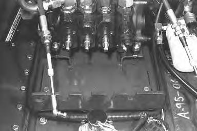
Remove the bucket position valves. (See Page 2–1.)
Remove the hydraulic control valve. (See Page 2–1.)
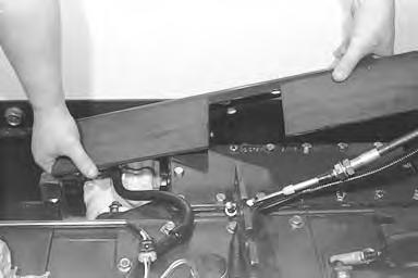
Remove the center cover and bracket. (See Page 4–31.)
Remove the rear cover [A]. (See Page 4–34.)
Remove the wheel assembly, hub and seal. (See Page 4–34.)
Remove the fluid from the chaincase. (See Page 4–30.)
Remove the bolts from the end plate onthe axle sprocket [B].
Installation: Put LOCTITE on the bolts and tighten to 210–230 ft.–lbs. (285–311 Nm) torque.
Remove the end plate and shims [C].
Install the Port–a–Power ram jack between the two rear sprockets. Push the axle out until the ram jack is at the end of the stroke. Add a spacer and push the axle out again. Repeat this procedure until the axle is out of the sprocket [D]
REAR AXLE, SPROCKET AND DRIVE CHAIN(Cont’d)
Removal (Cont’d)
Remove the chain from the sprockets and remove the chain from the chaincase [A]
Remove the rear sprocket form the chaincase [B]
Remove the axle and bearing from the axle tube [C]
Remove the bearing from the inside of the chaincase[D].
REAR AXLE, SPROCKET AND DRIVE CHAIN(Cont’d)
Removal (Cont’d)
Install the bearing cup puller tool into the axle tube [A] (MEL1203–13).
Pull the bearing cup from the axle tube [B]
Use
REAR AXLE, SPROCKET AND DRIVE CHAIN(Cont’d)
Removal (Cont’d)
Install the long threaded bolt into the axle tube. Install the correct size bearing cup driver. Install a washer and nut [A] (MEL1020–11).
Install the chaincase, install the new bearing cup, the driver tool, washer and nut [B] (MEL1202–12).
Have a second person hold the wrench on the nut in the chaincase [C].
Turn
.
REAR AXLE, SPROCKET AND DRIVE CHAIN(Cont’d)
Removal (Cont’d)
Use a press to remove the bearing form the axle [A]
Turn the axle around and press the new bearing into position [A].
Installation
NOTE:Pack the outer and inner axle bearing with wheel bearing grease before installation.
Install the axle into the axle tube [B].
Install the inner bearing [C].
Service parts chains are not assembled, use the following procedure:
Install the connector link with chain at work bench. Use chain link press tool (MEL1246) and install the connector link. Put tool in the vise and tighten to 300 ft.–lbs. (407 Nm) torque.
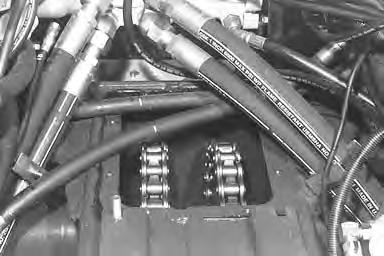
Install the chain into the chaincase [D].
REAR AXLE, SPROCKET AND DRIVE CHAIN(Cont’d)
Installation (Cont’d)
Put the sprocket into the chaincase [A].
Install the chain over the sprocket.
Start the splined end of the axle into the sprocket. Hit the outer end of the axle until the axle and sprocket are installed.
Install the plate and shims on the end of the sprocket[B]
Install a dial indicator on the axle tube and take axle end play reading [C].
The correct end play is between 0.00’’–0.006’’ (0,152 mm).
Install the axle seal and hub. (See Page 4–7.)
DRIVE CHAINS Front Drive Chain
Removal and Installation
The tools listed will be needed to do the following procedure:
MEL1246 – Chain Link Press
Remove the control center. (See Page 3–1.)
Remove the center cover with brakes.
Remove the brake disc.
Using the chain breaker tool, separate the chain [A]
NOTE:The front chains are heavy duty chains and the rear chains are regular drive chains.
Remove the chain from the chaincase [B]
Install a new chain.
Use wire to install the chain around the reduction gearcase sprocket [C].
Install the chain around the front sprocket.
Pull the chain together and install the connector link[D]
DRIVE CHAINS (Cont’d)
Front Drive Chain (Cont’d)
Removal and Installation (Cont’d)
Install the chain link press and connector plate on the chain [A].
Make sure the alignment is correct so that the connector plate will be installed straight.
NOTE:Press the connector link into position one pin at a time, then move to the next pin and press the link connector.
Put a torque wrench on the chain link press tool and tighten to torque listed below to pressthe connector plate into position [B].
Diamond Chain 300 ft.–lbs. (407 Nm) Tsubaki Chain 250 ft.–lbs. (339 Nm)
Rear Drive Chains
The rear drive chains cannot be separated and connector links pressed on because there is no clearance for the chain breaker tool or the chain link press. Use the Axle, Sprocket and Drive Chain procedure to replace the rear chain. (See Page 4–17.)
REDUCTION GEARCASE Removal and Installation
The tool listed will be needed to do the following procedure:
MEL1275 – Lift Brackets
OEM4126 – Sling

Raise the operator cab. (See Page 1–1.)
Remove the control panel. (See Page 3–1.)
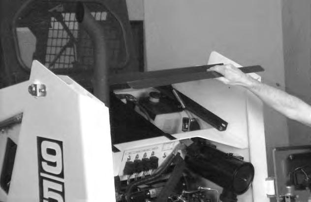
Remove the fuel tank on the side you are going toremove the gearcase. (See Page 5–1.)
Remove the nuts, on the outside of the loader, from the bracket which the fuel tank sets on [A].

Installation: Tighten the nuts to 220–245 ft.–lbs. (300–330 Nm) torque.
Remove the bracket from the loader [B]
Remove the hydrostatic motor from the gearcase. (See Page 3–1.).
Remove the front cover and the brake assembly. (See Page 4–3.).
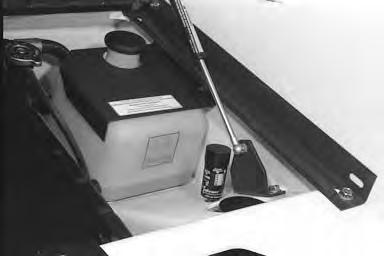
Remove the fluid from the chaincase [C].
NOTE:To remove the gearcase, you have to break the front chain.
Break the front chain. (See Page 4–23.)
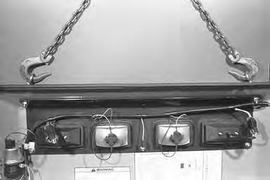
Install the lift brackets on the gearcase. Install a chain hoist on the lift brackets.
REDUCTION GEARCASE (Cont’d)
Removal and Installation (Cont’d)
Remove the ten bolts that fasten the gearcase to the chaincase [A]
Installation: Tighten the ten bolts to 220–245 ft.–lbs. (298–332 Nm) torque.
A
Lift the gearcase a small amount and slide to the rear of loader. Remove the rear chain.
Move the gearcase away from the chaincase and start to lift [B]
Turn the shaft of the gearcase down and keep lifting until it is out of the chaincase [C]
Installation: When installing the gearcase, put hi–tec on the O–ring to keep it from falling off the gearcase housing.
Disassembly and Assembly
Remove the housing cover [D]
REDUCTION GEARCASE (Cont’d)
Disassembly and Assembly (Cont’d)
Remove the four bolts and remove the end cap [A].
Remove the dust cover [B]
Remove the nap ring (Item 1) [C] and hub (Item 2) [C]
Remove the key from the shaft (Item 3) [C]
Shaft (Item 4) End Play 0.007’’ (0,17 mm) Max. Use shim (Item 5) (P/N 6565827) to get correct end play.
Shaft (Item 6) End Play 0.008’’ (0,20 mm) Max. Use shim (Item 7) (P/N 6565838) to get correct end play.
Shaft (Item 8) End Play 0.008’’ (0,20 mm) Max. Use snap ring (Item 9) (P/N 663834 or 6565844) to get correct end play.
Backlash between gears to be 0.005–0.010’’ (0,13–0,25 mm)
REDUCTION GEARCASE (Cont’d)
Disassembly and Assembly (Cont’d)
Remove the two snap rings [A].
Remove the bolts and plate (Item 1) [B].
Installation: Tighten the bolts to 65–70 ft.–lbs. (88–95 Nm) torque.
Remove the bolt and plate (Item 2) [B]
Installation: Tighten the bolt to 220–245 ft.–lbs. (300–330 Nm) torque.
Remove the bearings (Item 1) [C]
Remove the shaft (Item 2) [C]
Remove the snap ring, bearings and gear (Item 3) [C]
REDUCTION GEARCASE (Cont’d)
Disassembly and Assembly (Cont’d)
Remove the gear from the housing [A]
Make an inspection of all the bearings, cups and gears and replace as needed.
Use a press to remove and replace the bearing cups.
Assembly: Reverse the order of disassembly.
CHAINCASE FLUID Removal

Raise the operator cab. (See Page 1–1.)
Remove the control panel. (See Page 3–1.)
Remove the brake linkage and center cover. (See Page 4–31.)
Use a pump to remove the chaincase fluid [A]
Use only recommended fluid. (See Page 7–1.)
Chaincase Covers
Center Chaincase Cover Removal and Installation
Raise the lift arms and install the lift arm support. (See Page 1–1.)
Raise the operator cab. (See Page 1–1.)
Remove the control panel from the loader. (See Page 3–1.)
Remove the cross over tube (Item 1) [A] & [B] by removing the clamps (Item 2) [A] & [B] and the hoses (Item 3) [A] & [B].
Remove the shock bracket assembly (Item 1) [C] by removing the two (2) bolts (Item 2) [C]

Remove the cable mount bracket (Item 1) [D] by removing the two (2) bolts (Item 2) [D].
CHAINCASE COVERS (Cont’d)
Center Chaincase Cover Removal and Installation (Cont’d)
Disconnect the electrical connector (Item 1) [A] from the parking brake pedal sensor.
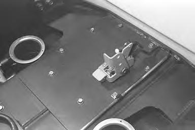
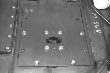
Remove the (2) mounting bolts (Item 1) [B] from the traction lock assembly (Item 2) [B] on the center chaincase cover.
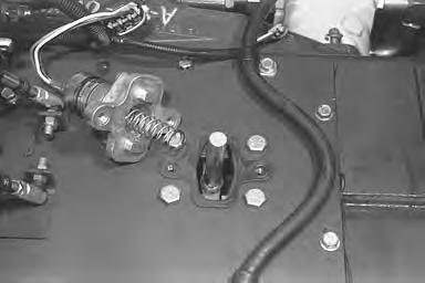
Installation: Tighten the mounting bolts for the traction lock assembly to 25–28 ft.–lbs. (34–38 Nm) torque.
Remove the traction lock assembly (Item 2) [C] from the chaincase cover.
CHAINCASE COVERS (Cont’d)
Center Chaincase Cover Removal and Installation (Cont’d)
Remove the remaining chaincase cover mounting bolts (Item 1) [A]

Installation: Tighten the cover mounting bolts to 25–28 ft.–lbs. (34–38 Nm) torque.
Remove the center chaincase cover form the loader [B]

Installation: The chaincase cover is sealed by using RTV sealant (Item 1) [B] installed onto the chaincase. Clean the surfaces of the chaincase and cover for proper adhesion.
Reverse the removal procedure to install the chaincase cover.
Front Chaincase Cover Removal and Installation
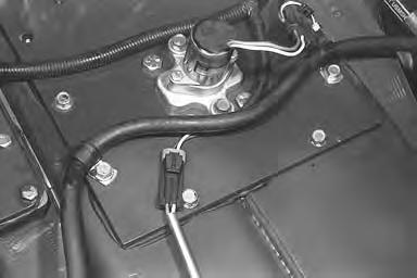
Disconnect the electrical connector (Item 1) [C] from the parking brake pedal sensor.
Remove the (8) front chaincase cover mounting bolts (Item 1) [D]
Installation: Tighten the cover mounting bolts to 25–28 ft.–lbs. (34–38 Nm) torque.
Remove the front chaincase cover (Item 2) [D] from the loader.
Installation: The front chaincase cover (Item 2) [D] is sealed by using RTV installed onto the chaincase. Clean the surfaces of the chaincase and cover for proper adhesion.
CHAINCASE COVERS (Cont’d)
Rear Chaincase Cover Removal and Installation
Raise the lift arms and install the lift arm support device. (See Page 1–1.)
Raise the operator cab. (See Page 1–1.)
Remove the control panel from the loader. (See Page 3–1.)
Remove the control valve from the loader. (See Page 2–1.)

Remove the tilt lock valve and bracket. (See Page 8–1.)
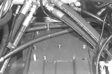
Remove the hose clamps (Item 1) [A] and move hoses (Item 2) [A].
Remove the bolts (Item 1) [B] from rear cover.
Lift rear chaincase cover from loader [C].
Installation: The chaincase cover is sealed by RTV sealant installed onto the chaincase. Clean the surface of the chaincase and the cover for proper adhesion.
Main Frame
Operator Cab
Removal and Installation
Remove the rubber stops (Item 1) [A] (both sides) by removing the screw (Item 2) [A]
Remove
OPERATOR CAB (Cont’d)
Removal and Installation (Cont’d)
Remove the pivot pins at the top [A] and the bottom [B] of the gas cylinders. Remove the gas cylinders.
Remove the operator cab pivot bolts [C] (both sides). Lift the operator cab with the chain hoist and remove fromthe loader
Installation: Tighten the pivot bolts to 25–35 ft.–lbs. (34–47 Nm) torque.
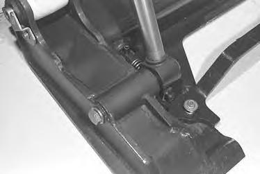
Operator Cab Gas Cylinder
Removal and Installation
Remove the rubber stops (both sides) [A]. (See Page 5–1.)
Raise the operator cab. (See Page 1–1.)
NOTE:Make sure to support the operator cab with a chain hoist when the gas cylinder isremoved so that the operator cab cannot tip forward.

Remove the pivot pins (Item 1) [B] at the top of the gas cylinder by removing the cotter pins (Item2) [B] and washers (Item 3) [B].
Remove the pivot pins at the bottom of the gas cylinder [C]
Remove the gas cylinder.
Cylinder contains high pressure gas. Do not open. Opening cylinder can release rod and cause injury or death.
Seat Bar
Removal and Installation
The tool listed is needed for the following procedure:
MEL1426
– Gas Spring Retainer Tool
Lower the operator seat bar.
Install the gas spring retainer tool on the gas cylinder (Item 1) [A]
Install the end of the tool that is bent at a 90 ° angle in the clevis of the cylinder as shown [B]

Install the curved end of the tool on the base end of the gas cylinder.
Secure the tool to the gas cylinder with a hose clamp (Item 2) [A].
Remove the cotter pin (Item 1) [B] from the clevis pin.
Remove the clevis pin (Item 1) [C] from the gas cylinder.
Use a 17/32 inch tappet wrench (Item 1) [D] to hold the ball joint on the gas cylinder.
Remove the mounting nut from the ball joint [D]
Installation: Be careful not to overtighten the mounting nut on the ball joint.
Remove the gas cylinder from the seat bar.
Cylinder contains high pressure gas. Do not open. Opening cylinder can release rod and cause injury or death.
W–2113–0288
Replace the gas cylinder if it malfunctions.
SEAT BAR (Cont’d)
Removal and Installation (Cont’d)
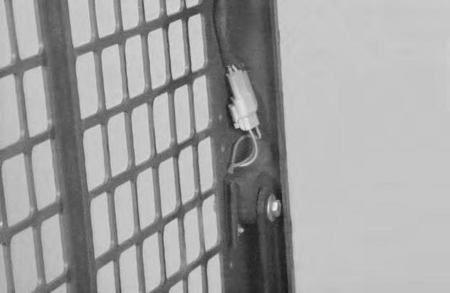
Disconnect the seat bar sensor connector (Item 1) [A].
Remove the seat bar mounting bolt (Item 1) [B] (both sides).
Installation: Tighten the seat bar mounting bolts to 25–28 ft.–lbs. (34–38 Nm) torque.
Remove the seat bar sensor mounting bolt (Item 2) [B] and nut.
Installation: Tighten the sensor mounting bolt to 80–90 in.–lbs. (9–10 Nm) torque.
Remove the sensor assembly from the magnetic bushing on the seat bar.
Installation: Be sure the two tabs on the pivot bushing are located in the slot on the cab as shown [C].

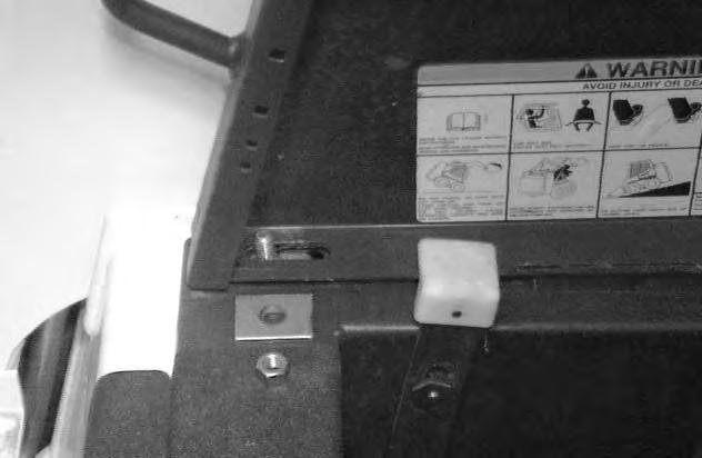
Pull both ends of the seat bar which are mounted to the operator cab, back from the mounting positions on the operator cab [D]

Remove the magnetic bushing mounting bolt, washer, magnetic bushing, plastic bushing and pivot bushing from the seat bar [D]. Refer to Page 8–1 for correct assembly procedure of the seat bar sensor assembly.
Remove the mounting bolt, gas cylinder mounting bracket, plastic bushing and pivot bushing from the seat bar [D]. Refer to Page 5–5 for correct assembly procedure of the gas cylinder mounting assembly.
SEAT BAR (Cont’d)
Removal and Installation (Cont’d)
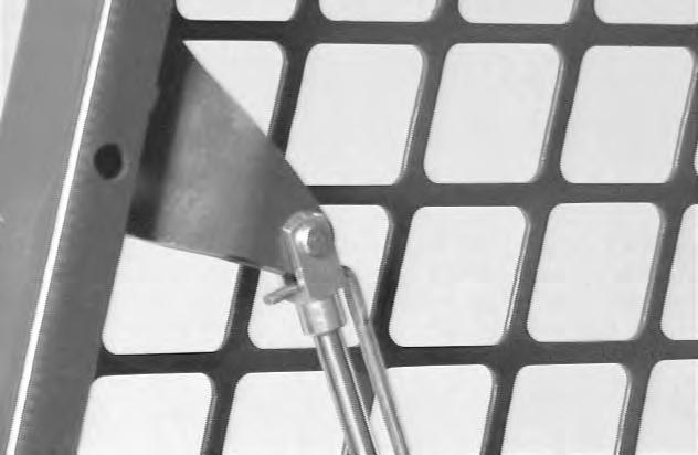
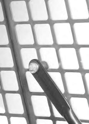
To remove the seat bar from the operator cab,the seat bar needs to be put in the correct location.
Use the squares in the right side of the operator cab side screen to locate the seat bar correctly [A]
Put the padded corner of the seat bar five squares back from the front of the operator cab side screen and four squares up from the bottom of the screen [A]
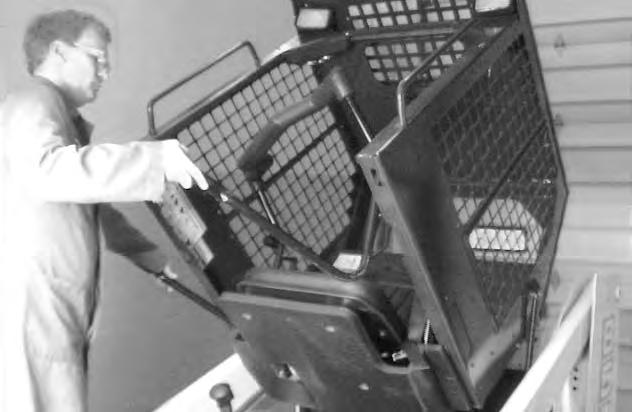
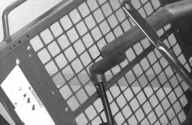
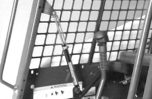
The arm of the seat bar (Item 1)[B] should also belocated outside of the operator cab, just below the bottom edge of the cab.
Grab both ends of the seat bar as shown and pull the left side of the seat bar out of the operator cab until the seat bar is free [B]
Remove the seat bar from the operator cab. Reverse removal procedure to install the seat bar.
See the following assembly procedure when installing the seat bar.
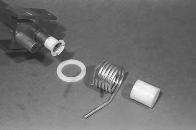
Assembly
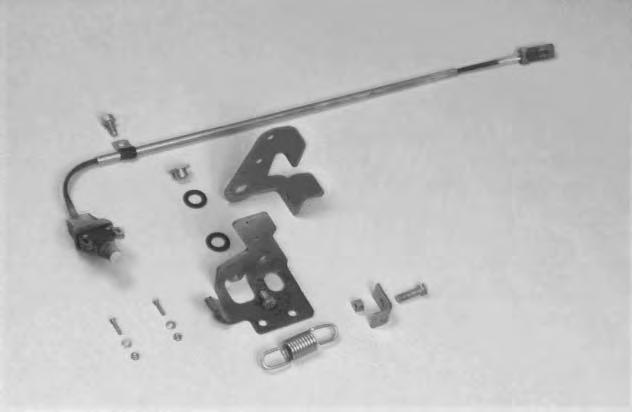
Assemble the parts as shown for the left side of the seat bar pivot assembly [C]:
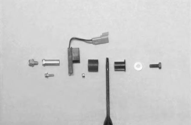
Mounting Bolt – (Item 1).
Washer – (Item 2).
Keyed Plastic Bushing – (Item 3).
Magnetic Bushing Assembly (Item 4).
Sensor Bracket – (Item 5).
Pivot Bushing – (Item 6).
Mounting Bolt – (Item 7).
Sensor Mounting Bolt (Item 8).
Sensor Mounting Nut (Item 9).
SEAT BAR (Cont’d) Assembly (Cont’d)
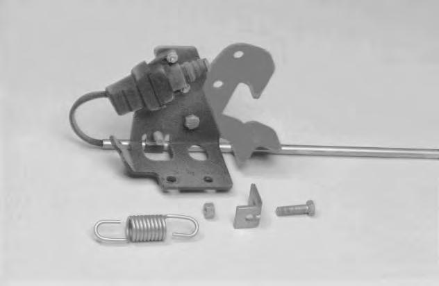
Assemble the parts as shown for the right side of the seat bar pivot assembly [A]:

Mounting Bolt (Item 1).
Pivot Bushing (Item 2).
Keyed Plastic Bushing (Item 3).
Gas Spring Mounting Bracket (Item 4). Mounting Bolt (Item 5).
Install the right side pivot assembly as shown. Tighten the mounting bolt (Item 1)[B] to 180–200 in.–lbs. (21–23 Nm) torque.
NOTE:Be sure the bend in the gas spring bracket faces in toward the operator when installing the gas spring bracket. Slide the bracket all the way forward so the front edge of the bracket fits tightly against the operator cab.

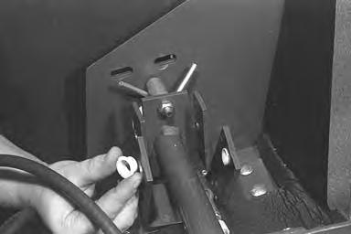
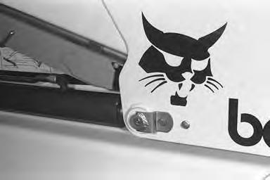
Compressing the Gas Cylinder
To compress the seat bar gas spring, it is necessary to use the gas spring retainer tool MEL1426.
Use the following procedure to compress the gas spring:
Cylinder contains high pressure gas. Do not open. Opening cylinder can release rod and cause injury or death.
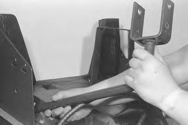
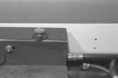
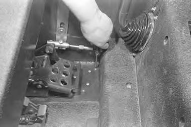
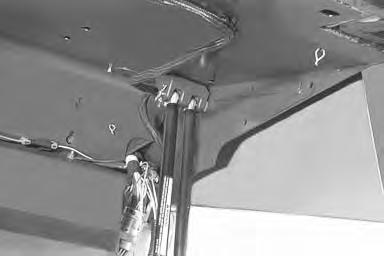
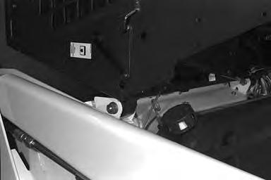
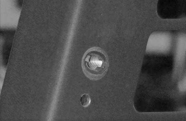
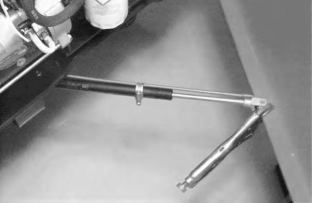
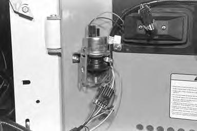
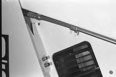
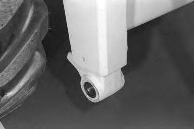
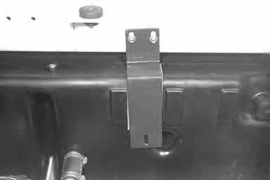
Open the rear door of the loader and install the gas spring (Item 1 – ball stud end)[C] in the hole located in the loader frame.
NOTE:Install the ball stud threads up through the hole and install a nut (Item 2) [C] on the ball stud.
Put the clevis end of the gas cylinder on the edge of the rear door as shown [C] and install a locking plier (Item 3) [C] on the bottom edge of the door to keep the gas cylinder from sliding along the edge.
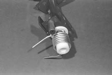
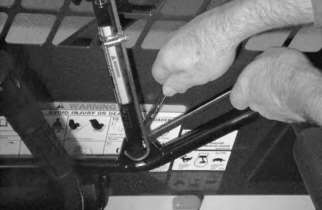
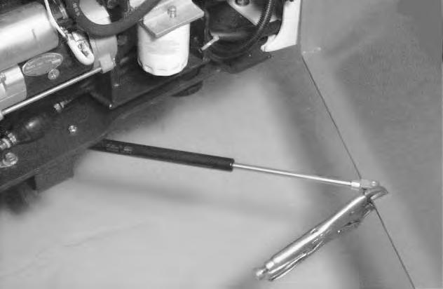
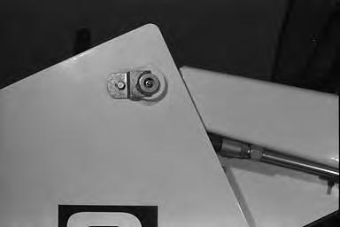
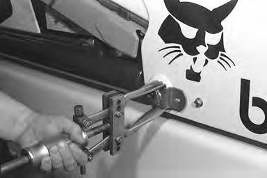
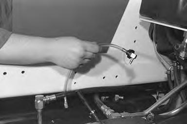
Pull the door in and compress the gas cylinder [D]
Install the retainer tool (Item 1) [D] with the 90 ° bend in the clevis of the rod end of the gas cylinder. Install the curved end of the tool around the base end of the gas spring.
Install the clamp (Item 2) [D] around the gas cylinder to hold the retainer tool in place. Remove the nut and remove the gas spring from the rear door.
REAR GRILL GAS CYLINDER Removal and Installation
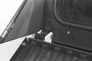
Lift the rear grill [A]. Add a support to prevent the grill from closing when the gas cylinder is removed.
Remove the retainer clips (Item 1) [B] at both of the ball joints ends. Remove the ball joints from the ends. Remove the cylinder.
Rear Door
Removal and Installation
Disconnect all the wire connectors (Item 1)[A] at the rear door.
Disconnect the plastic tube (Item 2) [A] at the ether start unit (if so equipped).

Install a chain hoist on the rear door using eye bolts [B]
Remove both hinge pins (Item 1) [C] using a punch and hammer.
Remove the rear door from the loader.
Lift Arms
Removal and Installation
When making repairs on hydrostatic and hydraulic systems, clean the work area before disassembly and keep all parts clean. Always use caps and plugs on hoses, tubelines and ports to keep dirt out. Dirt can quickly damage the system.
I–2003–0284
Put the Bob–Tach on the floor. Remove the Bob–Tach from the lift arms. (See Page 5–14.)
Remove the top tubeline clamp on the lift arms (Item 1) [A] (both sides).
Pull the tubelines down for clearance. Disconnect the hoses (Item 1) [B] from the tubelines (both sides).
Remove the bolt (Item 1) [D] from the pin retainer plate (both sides).
Installation: Tighten the bolt to 190–240 in.–lbs. (21–27 Nm) torque.
Remove the lift cylinder from lift arms. (See Page 2–1.)

LIFT ARMS (Cont‘d)
Removal and Installation (Cont‘d)
Use a puller and remove the pin at the rod end of the lift cylinder [A] (both sides).
Remove the bolt (Item 1) [B] at the lift arm pivot pins (both sides).
Use a hammer and punch and remove the pivot pins (Item 1) [C] (both sides).


Lift the lift arms using the chain hoist and remove them from the loader frame.
Installation
When installing the pins at the lift arms and rod end of lift cylinder, make sure to make alignment of the retainer plate to the mounting bolt hole [D].
BOB–TACH Removal and Installation
Put the Bob–Tach on the floor.
Remove the bolt and washer at the pin of the rod end of the tilt cylinder [A] (both sides).
Installation: Tighten the bolt to 125–140 ft.–lbs. (170–190 Nm) torque. Strike the bolt with a hammer, then re–torque the bolt to 125–140 ft.–lbs. (170–190 Nm) torque.
Install the bolt in the pin and hit the bolt with a hammer to remove the pin from the Bob–Tach frame [A] (both sides).

Remove the washer and bolt at the pin of the rod end of the tilt cylinder.
Remove the retainer plate bolt (Item 1) [B] at the Bob–Tach pivot pin (both sides).
Installation: Tighten bolt to 190–240 in.–lbs. (21–27 Nm) torque.
Use a hammer and punch and remove the pivot pin [C] (both sides).

BOB–TACH (Cont’d)
Removal and Installation (Cont’d)
Remove the Bob–Tach from the lift arms [A]
Installation
Remove the seal for the Bob–Tach pivot pins [B] (both sides).

Install new seals in the lift arms[C] (both sides), by driving them into place with mallet.
Bob–Tach Wedges
The Bob–Tach does not have to be removed from the lift arms to replace the wedges.

Push down on the lever. Remove the nut at the spring (Item 1) [D]
Installation: Tighten the nut to compress the spring to 5.9’’ (150 mm). Measured from the bottom of thenut to the center line of the clevis pin.
BOB–TACH (Cont’d)
Bob–Tach Wedges (Cont’d)
Remove the roll pin from the wedge.
Remove the wedge from the Bob–Tach frame [A]. Remove the spring from the wedge.
When installing the wedge in the Bob–Tach frame, make sure that the taper of the wedge is toward the rear of the Bob–Tach.
Bob–Tach Lever
Remove the nut (Item 1) [B] at the top of the spring.
Installation: Tighten the nut to compress the spring to 5.9’’ (150 mm). Measured from the bottom of thenut to the center line of the clevis pin.
Remove the bolt and spring (Item 2)[B] at the lever pivot.
Installation: Put LOCTITE on the bolt and tighten to 25–28 ft.–lbs. (34–38 Nm) torque.
Remove the Bob–Tach wedge. (See Page 5–16.)
Remove the lever (Item 1) [C] and washer (Item 2) [C] from the Bob–Tach frame.
Fuel Tanks
Removal and Installation, Left Side
Remove the control panel. (See Page 3–1.).
Remove the fuel from both tanks using a hand operated pump or a hydraulic transfer pump.
Remove the air bleed hose (Item 1) [A] and remove the wires (Item 2) [A] from the fuel sender.
Remove the remaining screws from the sending unit. Remove the fuel sender from the tank.
Put drain pans under the rear of the loader frame to prevent fuel from draining on the floor [B]
Remove the cross–over tube (Item 1) [C] between the fuel tanks by removing the clamps (Item 2) [C] and hose (Item 3) [C]
FUEL TANKS (Cont’d)
Removal and Installation, Left Side (Cont’d)
Remove the filter system and fuel tank bracket as a complete unit [A]
Remove the front fuel tank bracket [B].
Remove the fuel tank from the loader.
FUEL TANKS (Cont’d)
Removal and Installation, Right Side
Remove the control panel. (See Page 3–1.)
Remove the air bleed hoses and fuel suction hose [A].
Remove the fuel from both tanks using a hand operated pump or hydraulic transfer pump.
Put drain pans under the rear of the loader frame to prevent fuel from draining on the floor [B]
Remove the cross–over tube (Item 1) [C] between the fuel tanks by removing the clamps (Item 2) [C] and the hose (Item 3) [C]
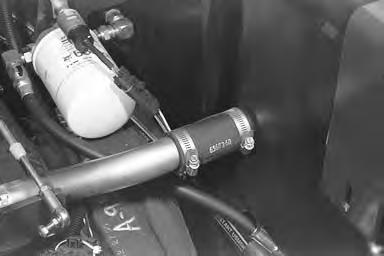
Loosen the clamp (Item 1) [D] and disconnect the fuel fill hose (Item 2) [D] from the fuel tank.

FUEL TANKS (Cont’d)
Removal and Installation, Right Side (Cont’d)
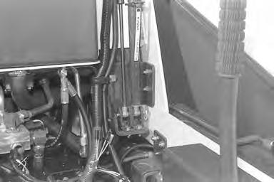
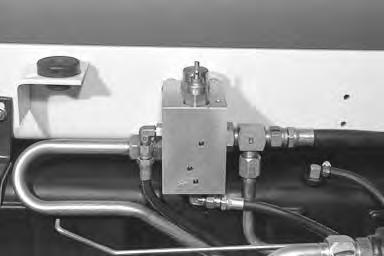
Disconnect all the tubelines (Item 1) [A] and hoses (Item 2) [A] from the lift arm by–pass control valve.
Remove the (2) two bolts that are on the outside of the frame and remove the lift arm by–pass control and remove from the loader [B].
Remove the front fuel tank bracket by removing the nuts (Item 1) [C]
Remove the fuel tank from the loader.
Fuel Tank Pick–Up Hose
Disconnect the fuel suction hose. Using a pliers, pull the fuel pick–up hose and screen from the tank [D].

FUEL TANKS (Cont’d)
Fuel Tank Pick–Up Hose (Cont’d)
Remove the rubber grommet form the fuel tank.
Remove the elbow fitting from the pick–up hose.
Install
Install
Reinstall
Main Frame
Main Frame Bolts
If the main frame is removed from the chaincase, re–install the bolts and nuts that fasten the main frame and chaincase together, tighten the bolts to 220–245 ft.–lbs. (300–332 Nm) torque [A]
NOTE:Check that the seat bar pedal locks are adjusted correctly. (See Page 3–1.)
WIRING DIAGRAM (P/N 6724786) Sheet 1 of 4
Operator Cab (Harness 6707665 Rev. C)
953 BICSTM
(Printed November 1995)
Legend
WIRING DIAGRAM (P/N 6724786) Sheet 1 of 4 Operator Cab (Harness 6707665 Rev. C)
(Printed November 1995) 953
WIRING DIAGRAM (P/N 6724786) Sheet 2 Of 4 Engine
(Harness 6594891 Rev. E or 6597224)
(Printed November 1995)