9 minute read
PREVENTIVE MAINTENANCE (Cont’d)


Service Schedule
Maintenance work must be done at regular intervals. Failure to do so will result in excessivewear and early failures. The service schedule is a guide for correct maintenance of the Bobcat loader.
Instructions are necessary before operating or servicing machine. Read Operation Maintenance Manual, Handbook and signs (decals) on machine. Follow warnings and instructions in the manual when making repairs, adjustments or servicing. Check for correct function after adjustments, repairs or service. Failure to follow instructions can cause injury or death.
Engine Oil Check the oil level & add oil as needed.
Air Cleaner Check condition indicator. Service only when required.
Engine Cooling SystemClean debris from oil cooler, radiator & grill. Check coolant level cold in recovery tank. Add coolant as needed.
Lift Arms, Cylinder, Bob–Lubricate with multi–purpose lithium based grease (14 places).
Tach Pivot Pins & Wedges
Engine Air System Check for leaks & damaged components.
Tires Check for damaged tires & correct air pressure.
Seat Belt, Seat Bar & PedalCheck the condition of seat belt. Check the seat bar & pedal Interlocks interlocks for correct operation. Clean dirt & debris from movingparts.
Bobcat Interlock ControlCheck BICS™ functions. Clean dirt, debris or bjects from under System (BICS™) or behind seat as required.
Safety Signs & SafetyCheck for damaged signs (decals) & safety tread. Replace any Tread signs or safety treads that are damaged or worn.
Operator Cab Check the fastening bolts, washers & nuts. Check the condition of cab. Remove debris from the pedal area through the clean–out holes.
Fuel Filter Remove the trapped water.
Hydraulic Fluid, Hoses &Check fluid level & add as needed. Check for damage & leaks.
Tubelines Repair & replace as needed.
Final Drive TransmissionCheck oil level.
(Chaincase)
Battery Check battery for damage, hold down, cables, connections & electrolyte level. Add distilled water as needed.
Control Pedals & SteeringCheck for correct operation. Repair or adjust as needed.
Wheel Nuts Check for loose wheel nuts & tighten to 320–350 ft.–lbs. (434–475 Nm) torque.
Parking Brake Check operations of the parking brake.
Alternator Belt Check tension & adjust as needed.
Engine Oil & Filter Replace oil & filter. Use CD or better grade oil and Melroe filter.
Spark Arrestor MufflerClean the spark chamber.
Engine/Hydro. Drive BeltCheck gap at rod nuts.
Fuel Filter Replace filter element & In–Line fuel filter
Steering Shaft Grease fitting & oil the cross–shaft.
Hyd./Hydro. Filters Replace the filter elements.
Hydraulic Reservoir Replace the reservoir breather cap.
Breather Cap
Final Drive TransissionReplace the oil in the chaincase.
Hydraulic Reservoir/Replace the fluid. Replace the case drain filter.
Case Drain Filter
Bobcat Interlock ControlCheck lift arm by–pass control.
System (BICS™)
Check wheel nut torque every 8 hours for the first 24 hours. Also replace hydraulic/hydrostatic filter element when the transmission warning light comes ON. Or every 12 months.
*Check every 8 hours for the first 40 hours of operation. First oil and filter change must occur at 50 hours; 100 hours thereafter.
Revised Feb. 97
Preventive Maintenance
Instructions are necessary before operating or servicing machine. Read Operation & Maintenance Manuals, Handbook and signs (decals) on machine. Follow warnings and instructions in the manuals when making repairs, adjustments or servicing. Check for correct function after adjustments, repairs or service. Failure to follow instructions can cause injury or death.
W–2003–1289
Wear safety glasses to prevent eye injury when any of the following conditions exist:
• When fluids are under pressure.
• Flying debris or loose material is present.
• Engine is running.
• Tools are being used.
LIFTING AND BLOCKING THE LOADER Procedure
Always park the loader on a level surface.
W–2019–1285
Put jackstands under the front axles and rear corners of the frame before running the engine for service. Failure to use jackstands can allow the machine to fall or move and cause injury or death.
W–2017–0286
Lower the lift arms, stop the engine. Put the floor jack under the rear of the loader. Lift the rear of the loaderand install jackstands [B]
Put the floor jack under the front of the loader. Lift the front of the loader and install jackstands under the axle tubes [C]
NOTE:Make sure the jackstands do not touch the tires.
TRANSPORTING THE LOADER Procedure
Adequately designed ramps of sufficient strength are needed to support the weight of the machine when loading onto a transport vehicle. Wood ramps can break and cause personal injury.
W–2058–0494
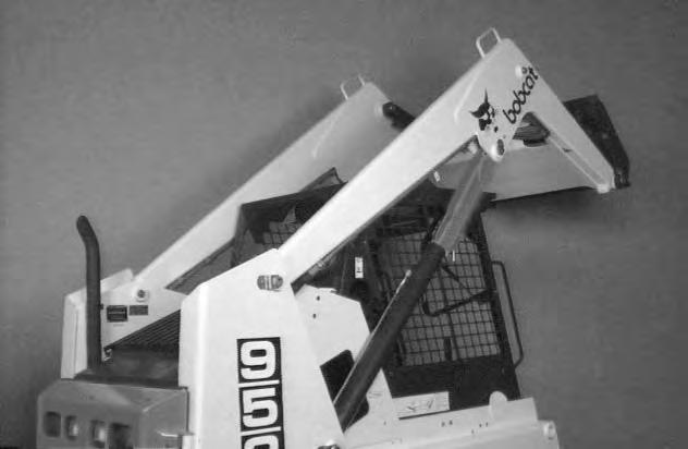
A loader with an empty bucket or no attachment must be loaded backward onto the transport vehicle [A]
Be sure the transport and towing vehicles are of adequate size and capacity.
Use the following procedure to fasten the Bobcat loader to the transport vehicle to prevent the loader from moving during sudden stops or when going up ordown slopes [B].
Lower the bucket or attachment to the floor. Stop the engine. Engage the parking brake. Install chains at the front and rear loader tie down positions (Inset)[B]. Fasten each end of the chain to the transport vehicle and tighten the chain with a chain tightener.
TOWING THE LOADER Procedure
To prevent damage to the loaders hydrostatic system, the loader must be towed only a short distance at slow speed. (Example: Moving the loader onto a transport vehicle.)
The towing chain (or cable) must be rated at 1–1/2 times the weight of the loader. (See Specification, Page 9–1.)
• Turn the key switchto ON and press the Traction Lock Override button.
• Tow the Bobcat at 2 MPH (3,2 km/hr.) or less for not more than 25 feet (7,6 meters).
If the electrical system is not functioning part of the brake system must be disassembled to move the loader. (See Traction Lock removal and installation procedure, Page 8–1.)
Never work on a machine with the lift arms up unless the lift arms are secured by a lift arm support device. Failure to use an approved lift arm support device can allow the lift arms or attachment to fall and cause injury or death.

Engaging the Lift Arm Support Device
Maintenance and service work can be done with the lift arms lowered. If the lift arms must be raised for service, use the following procedure:
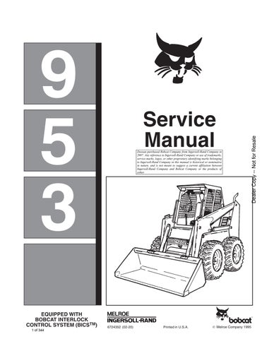
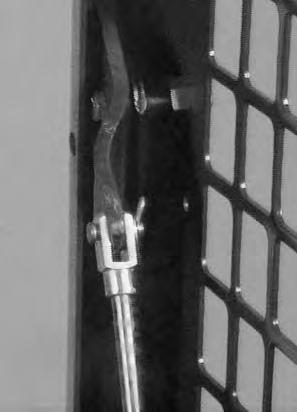
Disconnect the spring (Item 1) [A] from the lift arm support device retaining pin (Item 2) [A] hold onto the support device and remove the retaining pin.
Lower the lift arm support device on top of the lift cylinder. Hook the free end of the spring to the lift arm support device so there will be no interference with the support device engagement [B]
With the operator in the seat, seat belt fastened and seat bar lowered, start the engine.
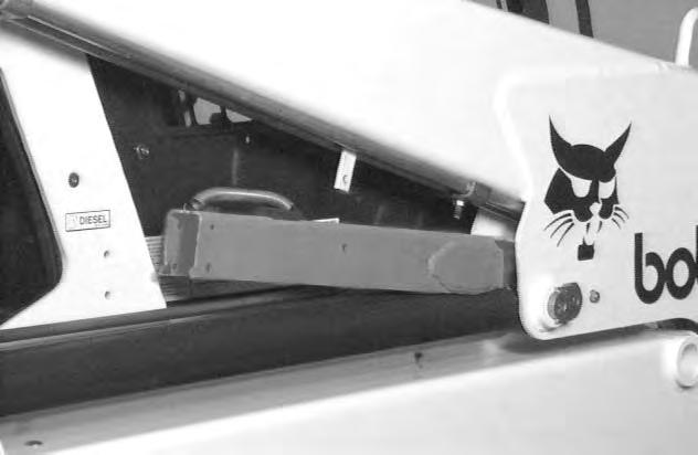
Raise the lift arms, until the lift arm support device lowers onto the lift cylinder rod [C].
Lower the lift arms slowly until the support device is held between the lift arm and the lift cylinder. Stop the engine. Raise the seat bar and foot controls until both controls lock.
Install pin (Item 1) [C] into the rear of the lift arm support device below the cylinder rod.
Disengaging the Lift Arm Support Device
Remove the pin from the lift arm support device.
Connect the spring (Item 1) [D] from the lift arm support device to the bracket below the lift arms.
With the operator in the seat, seat belt fastened and seat bar lowered, start the engine.
Raise the lift arms a small amount and the spring will lift the support device off the lift cylinder rod. Lower the lift arms. Stop the engine.
Raise the seat bar and move foot controls until both controls lock.
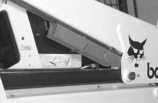
Disconnect the spring from the bracket.Raise the support device into storage position and insert pin through lift arm support device and bracket [A]
Connect spring to pin [A].
OPERATOR CAB Description
The Bobcat loader has an operator cab (ROPS and FOPS) as standard equipment to protect the operator from rollover and falling objects. Check with your dealer if the operator cab has been damaged. The seat belt must be worn for roll over protection.
ROPS/FOPS – Roll Over Protective Structure per SAE J104 and ISO 3471, and Falling Object Protective Structure per SAE J1043 and ISO 3449, Level l. Level ll is available.
Level l – Protection from falling bricks, small concrete blocks and hand tools encountered in operations such as highway maintenance, landscaping, and other construction site services.
Level ll – Protection from falling trees, rocks; for machines involved in site clearing, overhead demolition or forestry.
Never modify operator cab by welding, grinding, drilling holes or adding attachments unless instructed to do so by Melroe Company. Changes to the cab can cause loss of operator protection from rollover and falling objects, and result in injury or death.
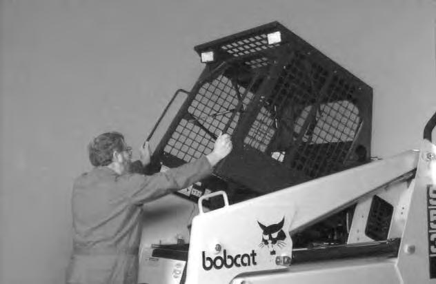
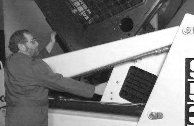
Raising the Operator Cab
Stop the loader on a level surface. Lower the lift arms. If the lift arms must be up while raising the operator cab, install the lift arm support device. (See Page 1–6.)
Before the cab or the lift arms are raised for service, jackstands must be put under the rear corners of the frame. Failure to use jackstands may allow the machine totip backward causing injury or death.
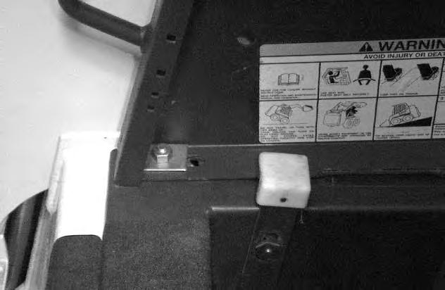
Loosen the nut (Item 1)[A] (both sides) at the front corner of the operator cab.
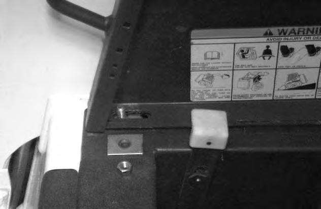
Remove the nut and plate (both sides) [B]
Lift on the grab handle and bottom of the operator cab slowly until the cab latching mechanism engages and the cab is all the way up [C]
OPERATOR CAB (Cont’d)
Lowering the Operator Cab

NOTE:Make sure the seat bar is fully raised or lowered when lowering the cab.
Pull down on the bottom of the operator cab until it stops at the latching mechanism. Release the latching mechanism and pull the cab all the way down [A].
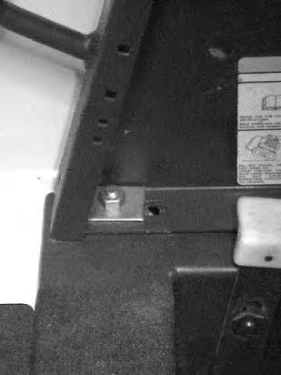

Install the plate and nut (both sides) [B]
Tighten the nuts to 40–50 ft.–lbs. (54–68 Nm) torque.
Emergency Exit
The front opening on the operator cab and rear window provide exits.
To exit through the rear window, use the following procedure:

Pull on the tag on the top of the rear window to remove the rubber cord [C]
Push the rear window out of the rear of the operator cab. Exit through the rear of the operator cab [D]
OPERATOR CAB (Cont’d)
Emergency Exit (Cont’d)
NOTE:When an Operator Cab Enclosure Kit (optional) is installed, the window of the front door can be used as an emergency exit. [A]

Pull the plastic loop at the top of the window in the front door.
Push the window out with your foot.
Seat Bar Restraint System
Description
The seat bar restraint system hasa pivoting seat bar with arm rests and has spring loaded interlocks forthe lift and tilt control pedals. The operator controls the use of the seat bar. The seat bar in the down position helps to keep the operator in the seat. The interlocks require the operator to lower the seat bar in order to operate thefoot pedal controls. When the seat bar is up, the lift and tilt pedals are locked when returned to the neutral position.
Seat Bar Inspection
Sit in the seat and fasten the seat belt. Engage the parking brake. Pull the seat bar all the way down. Start the engine. Operate each foot pedal to check both the lift and tilt functions. Raise the lift arms until the bucket is about 2 feet (600 mm) off the ground.
Raise the seat bar. Try to move each foot pedal. Pedals must be firmly locked in neutral position. There must be no motion of the lift arms or tilt (bucket) when the pedals are pushed.
Pull the seat bar down, lower the lift arms. Operate the lift pedals. While the lift arms are going up, raise the seat bar and the lift arms should stop.
Lower the seat bar, lower the lift arms and place the bucket flat on the ground. Stop the engine. Raise the seat bar and operate the foot pedals to be sure that the pedals are firmly locked in the neutral position. Unbuckle the seat belt.
Seat Bar Maintenance
See the Service Schedule Page 1–3 and on the loader for correct service interval.
Clean any debris or dirt from the moving parts [B] & [C]. Inspect the linkage bolts and nuts for tightness. The correct torque is 25–28 ft.–lbs. (34–38 Nm).

If the seat bar system does not function correctly, check for free movement of each linkage part. Check for excessive wear. Adjust pedal control linkage. Replace parts that are worn or damaged. Use only genuine Melroe replacement parts.
Avoid Injury Or Death
The seat bar system must lock the lift and tilt control pedals in neutral when the seat bar is up. Service the system if pedals do not lock correctly.
Rear Door
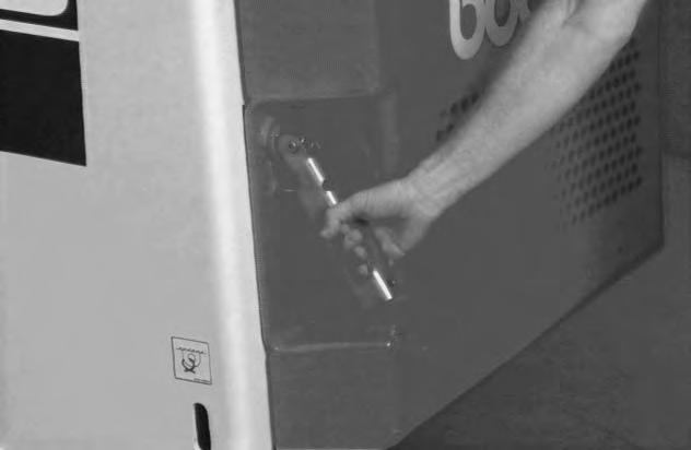
Opening the Rear Door
Avoid Injury Or Death
Stop, cool and clean engine of flammable material. Never service or adjust loader with engine running unless instructed to do so in manual.
W–2061–0887
Pull up on the door latch [A] and turn it to open the rear door [B].
NOTE:If a rear scarifier attachment is installed, prevent damage to the rear door by making sure the rear door is closed and the latch pin lock is installed before the rear scarifier is raised during loader operation.
Keep the rear door closed when operating the machine. Failure to do so could seriously injure a bystander.
W–2020–1285
Adjusting the Rear Door Latch

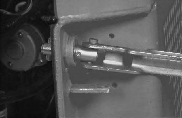
Loosen the set screw (Item 1) [C]. Loosen the nut (Item 1) [D]
Turn the bolt (Item 2) [D] in or out until the door contacts both the top and the bottom of the loader frame with the lever in the latched position.
NOTE:It takes approximately 50 lbs. (20 kg) of force to push the lever down when the latch is correctly adjusted.
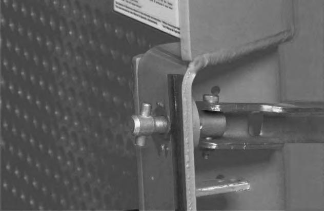
With the set screw up, the flanges on the bolt must be to the side so that the set screw aligns with the flat surface of the bolt.
Tighten the set screw (Item 1) [C]
Tighten the nut (Item 1) [D] to 65–70 ft.–lbs. (88–95 Nm) torque.