TESTING STARTER MOTOR
Starter Relay Solenoid TESTING
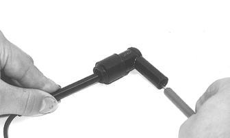
1. Disconnect the solenoid connector from the main wiring harness. 2. Place the ohmmeter leads across the solenoid coil terminals. The ohmmeter must read 3-5 ohms. NOTE: An in-line ammeter would measure between
2 and 4 amps of solenoid coil current flow with the battery connected.
CAUTION NEVER connect an in-line ammeter with the large starter cables because the 200 amps of current flow will instantly damage most ammeters.
Starter Motor REMOVING
NOTE: Before installing the starter motor, perform test to ensure proper operation using the following procedure.
1. Attach a black jumper cable to a good ground on the starter. 2. Attach the opposite end of the black jumper cable to the negative post of a good 12-volt battery. 3. Attach the red jumper cable to the positive post of the battery. 4. Holding the starter firmly down on a work bench, touch the red jumper cable to the positive cable stud of the starter.
! WARNING Be sure to keep clear of the pinion gear area as it will spin at a high RPM when the red jumper cable is touched to the positive stud. Personal injury may result if contact is made with the spinning pinion gear.
INSTALLING
1. Secure the starter motor using the two cap screws. Tighten to 11 N-m, 1.1 kg-m (8 ft-lb).
NOTE: The engine must be removed from the chassis in order to remove the starter motor.
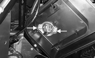
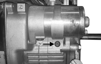
1. Remove the screw securing the starter motor strap to the crankcase.
ZR-261
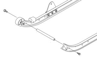
2. Secure the starter motor strap to the crankcase using the existing screw (threads coated with blue Loctite #243). Tighten to 11 N-m, 1.1 kg-m (8 ft-lb). ZR-262
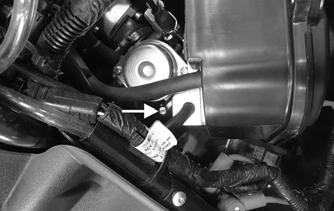
2. Remove the cap screws securing the recoil and the magneto cover. 3. Remove the two cap screws securing the starter motor to the crankcase. Remove the starter motor.
ZR-262
ZR-261
69