19 minute read
Fuel System

Troubleshooting Engine
Problem: Engine Does Not Start (No Spark at Spark Plug) Condition Remedy
1. Ground connections dirty — loose 1.Check all ground connections — clean and tight 2. Wiring harness shorting — disconnected 2.Repair — replace — connect wiring harness 3. Emergency stop switch in DOWN position — malfunction- 3.Move switch to UP position — test/replace ignition key ing switch/emergency stop switch 4. Tether cord improperly secured to tether switch — malfunc- 4.Properly secure cord to the switch — test/replace switch tioning 5. Spark plug fouled — damaged 5.Clean — replace spark plug
Problem: Engine Does Not Start (No Fuel at Cylinder) Condition Remedy
1. Gas tank empty 1.Fill tank 2. Gasoline contaminated 2.Replace gasoline 3. Fuel hose broken — pinched 3.Replace — service hose 4. Gas-tank vent — hose obstructed 4.Remove obstruction — replace vent — hose 5. Shut-off valve obstructed — damaged 5.Remove obstruction — replace shut-off valve 6. Compression absent 6.Repair — replace damaged — worn engine components
Problem: Engine Does Not Start (Fuel Does Not Ignite) Condition Remedy
1. Valve clearance poor 1.Inspect valves 2. Spark absent 2.Check for spark — see No Spark at Spark Plug sub-section 3. Compression low 3.Service engine 4. Engine flooded 4.Clear engine (using a shielded safety stand, elevate the rear of the snowmobile and hold throttle full-open) 5. Gasoline contaminated 5.Clean tank and entire fuel system
Problem: Engine Does Not Idle Condition Remedy
1. Throttle stop screw turned out too far 1.Adjust throttle stop screw 2. Idle fuel adjuster screw out of adjustment 2.Adjust idle fuel adjuster screw 3. Air silencer obstructed 3.Clean air silencer 4. Drive clutch dirty 4.Clean drive clutch
Problem: Engine Loses Power Condition Remedy
1. Spark plug fouled 1.Replace spark plug 2. External coil faulty 2.Service — replace coil 3. Gas tank vent — hose obstructed 3.Service — replace vent hose 4. Compression low 4.Service engine 5. Muffler restricted 5.Inspect muffler
Problem: Engine Overheats Condition Remedy
1. Drive system adjusted incorrectly — worn — damaged 1.Troubleshoot — adjust drive system 2. Rings/grooves carboned 2.Clean — replace rings — pistons 3. Exhaust obstructed 3.Remove obstruction 4. Compression low — absent 4.Repair — replace damaged — worn engine components 5. Engine shroud obstructed 5.Clean shroud
Problem: Engine Backfires Condition Remedy
1. Spark plug fouled — damaged 1.Clean — replace spark plug
Problem: Engine Stops Suddenly Condition Remedy
1. Gas tank empty 1.Fill tank 2. Spark absent 2.See No Spark at Spark Plug sub-section 3. Fuel filter obstructed 3.Replace filter 4. Gas tank shut-off valve in OFF position 4.Turn on valve 5. Fuel hose obstructed — broken — pinched 5.Remove obstruction — repair — replace fuel hose 6. Ignition coil faulty 6.Replace ignition coil 7. Engine seized 7.Overhaul engine 8. Oil level low 8.Add recommended oil
Fuel System
This section has been organized for servicing the fuel system. The technician should use discretion and sound judgment when removing/disassembling and assembling/ installing components.
! WARNING
Whenever any maintenance or inspection is made on a fuel system when there may be fuel leakage, there should be no welding, smoking, open flames, etc., in the area.
Pre-Maintenance Checks
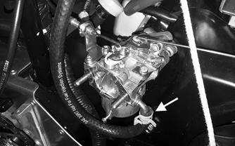
Before troubleshooting the fuel system, several simple checks should be performed. Many times what appears to be a serious problem is only a minor one. 1.Make sure the gas tank shut-off valve was in the
OPEN position and check for fuel flow from the tank to the carburetor. 2.Turn the shut-off valve to the CLOSED position; then remove the in-line fuel filter. If the filter is dirty, replace the filter. 3.Install a new filter making sure the arrow on the filter is directed toward the engine. 4.Check the gas tank fuel and vent hoses to ensure that all are correctly connected; then check for cracks. If any cracks are evident in the hoses, replace them making sure none are against any hot or moving parts. Hoses must fit tightly. 5.Check the carburetor float chamber by loosening the drain screw (I) and inspect it for water or debris. If seen, clean by removing the float chamber cap screw and cleaning the float chamber. 6.When ready for operation, turn the shut-off valve to the OPEN position.
In-Line Fuel Filter
! WARNING
Whenever any maintenance or inspection is made on a fuel system when there may be fuel leakage, there should be no welding, smoking, open flames, etc., in the area.

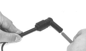
Arctic Cat recommends that the in-line fuel filter be checked once a month. The filter is located in the fuel hose between the gas tank and fuel pump. The only cleaning possible is to back-flush the filter using clean gasoline. To check, clean, or replace the filter, use the following procedure: 1.Using a suitable hose clamping pliers, pinch off the fuel hose between the gas tank and the filter. 2.Remove and discard the clamps; then slowly remove the fuel hoses from the fuel filter. Properly dispose of the excess fuel from the filter. 3.Install the in-line fuel filter in the fuel hose so the arrow on the filter points toward the fuel pump.
Make sure the fuel hoses fit tightly on the filter. If a fuel hose does not fit tightly, cut 6 mm (1/4 in.) from the end of the fuel hose; then install on the filter.
Install new clamps and remove the clamping pliers.
CAUTION
The fuel hoses must fit tightly on the fuel filter. If the fuel hose length doesn’t permit this procedure, replace the fuel hose. Also, after installing the fuel hoses on the filter, check to be sure that the fuel hoses do not contact any hot or rotating components.
Carburetor (B-25)
REMOVING
1.Loosen the clamp securing the intake boot to the carburetor.
ZR-323
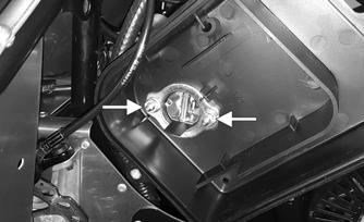
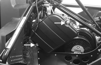
2.Pull the recoil starter rope out for enough to tie a slip-knot in the starter rope below the steering support and allow the rope to slowly retract against the recoil starter. 3.Remove the two cap screws securing the air box bracket to the top of the motor. Remove the air box assembly. Account for two hoses.
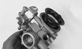
4.Lift up on the butterfly lever; then remove the end of the throttle cable from the lever. Remove the throttle lever from the bracket.

ZR-313
5.Loosen the screw securing the carburetor to the engine; then remove the carburetor away from the engine and disconnect the fuel line and the choke cable.
ZR-314

ZR-315
DISASSEMBLING
1.Remove the three screws securing the float chamber body to the bottom of the carburetor. Remove the body and account for an O-ring.

ZR-316
2.Remove the main jet and the nozzle from the carburetor tower. 3.Remove the screw securing the float pin; then remove the float and the needle jet as an assembly.

ZR-317
4.Remove the pilot jet. 5.Remove the two screws securing the diaphragm cover. Remove the cover and account for a spring.

ZR-318
6.Remove the diaphragm and needle assembly from the carburetor body.
ZR-319
CLEANING
CAUTION
DO NOT place any non-metallic components in partscleaning solvent or carburetor cleaner because damage or deterioration will result.
1.Place all metallic components in a wire basket and submerge in carburetor cleaner. 2.Soak for approximately 30 minutes; then rinse with fresh parts-cleaning solvent. 3.Wash all non-metallic components with soap and water. Rinse thoroughly. 4.Dry all components with compressed air only making sure all holes, orifices, and channels are unobstructed. 5.Blow compressed air through all hoses to remove any obstructions. ! WARNING
Always wear safety glasses when drying components with compressed air.
CAUTION
DO NOT use wire or small drill bits to clean carburetor orifices, holes, or channels. Distorted or damaged orifices, holes, or channels can result in poor carburetor operation.
INSPECTING
1.Inspect the mixing body and jet orifices for cracks, nicks, stripped threads, and any other imperfections in the casting. 2.Inspect the float for perforations or damage. 3.Inspect the gaskets for distortion, tears, or noticeable damage. 4.When applicable, inspect the idle fuel adjuster screw, needle jet assembly, and pilot jet for wear, damage, or distortion. 5.Inspect the nozzle and main jet for obstructions or damage. CAUTION
An air leak between the carburetor and engine will cause a lean condition and poor engine performance.
7.Inspect the condition of the throttle return spring. CHECKING FLOAT HEIGHT
1.Remove the cap screws securing the float chamber; then remove the float chamber from the carburetor and account for the gasket. 2.With the carburetor in an upside-down position, lift the float so the tip of the float lightly contacts the float arm; ensure the need spring is not compressed, then measure the float height from the body of the carburetor and underside of the float. Measurement should be 8 mm (0.31”).
ZR-320
CAUTION
Do not bend the float in an attempt to adjust the height. Correct float height is obtained by replacing the needle jet assembly and/or the float.
ASSEMBLING
1.Install the pilot jet, needle jet nozzle, and the main jet. Tighten securely. 2.Install the float assembly and needle jet and secure using the existing screw. Tighten securely.
ZR-317
3.Secure the float chamber body to the bottom of the carburetor using the existing three screws. Tighten securely.
ZR-316
4.Before installing the diaphragm and need assembly into the carburetor, push the diaphragm down. Install the assembly into the carburetor until the diaphragm contacts the groove in the carburetor. While holding the slide up from inside, install the spring and cover.
Secure using the existing screws. Tighten securely.

ZR-315
ZR-314
ZR-334
ZR-318
INSTALLING
1.Install the choke cable into the carburetor. Tighten until snug. Making sure the fuel screen is properly installed and clean, install the fuel hose onto the fitting and secure using the existing clamp. 2.Install the carburetor into the engine boot and secure using the existing screw. Tighten securely.
ZR-315
3.Lift up on the butterfly lever; then install the end of the throttle lever into the opening in the lever. Thread the jam nut of the cable into the bracket. Tighten securely. Install the boot over the jam nut.
ZR-313
4.With the clamp installed onto the intake boot, position the boot over the carburetor and align the bracket with the mounting locations on the engine.
Secure the bracket and clamp over the hose using two cap screws. Tighten to 16 N-m, 1.6 kg-m (12 ftlb).
ZR-322
5.Tighten the clamp securing the intake boot to the carburetor; then route the larger hose from the air cleaner case to the hole in the engine head cover.
Route the smaller hose from the carburetor into the intake bracket.
ZR-323
6.Route the recoil rope through the intake bracket up through the steering support; then install through the recoil handle and secure with a knot.
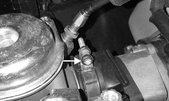
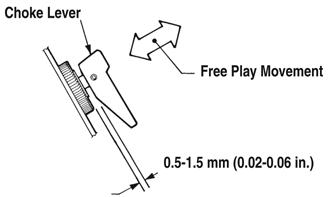
ADJUSTING Checking/Adjusting Engine Choke Cable 1.With the engine choke lever in the OFF position, measure the free play between the lever and the housing. Measurement should be 0.5-1.5 mm (0.020.06 in.).
ONS-182
2.If adjustment needs to be made, loosen the jam nut on the adjustment fitting; then turn the adjusting nut inward to increase the gap or outward to decrease the gap.

ZR-307
3.Tighten the jam nut securely; then install the rubber cover over the adjustment fitting. NOTE: If the choke cable is adjusted too tight, the
engine will idle poorly when it reaches operating temperature.
Checking/Adjusting Engine Idle NOTE: When setting the engine idle, the RPM will
vary depending on the temperature. If checking at room temperature, idle RPM will be lower than when checking outside in colder weather. It is recommended to have an idle speed of 1800 (± 50) RPM in running (winter) conditions.
To achieve the desired 1800 (± 50) RPM idle speed using a tachometer, use the following procedure: 1.Elevate the rear of the machine so the track is not on the ground; then connect the tachometer and start the engine to verify where the idle RPM is set. 2.If idle is 1800 (± 50) RPM, no adjustment is needed.
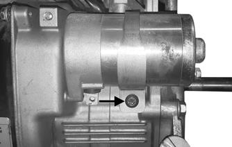
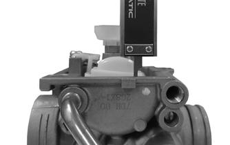
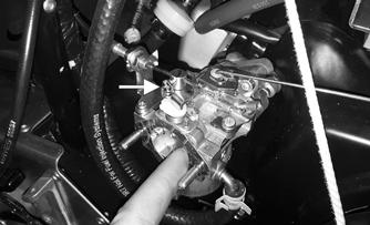
3.If RPM adjustment is needed, start by adjusting the idle speed screw located on the front side of the carburetor.
ZR-302
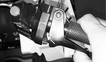
4.When the proper idle speed is maintained, verify when releasing the throttle lever that the idle switch in the control housing is compressed. If the switch is not compressed the engine will shut down when the throttle lever is released.
ZR-089A

NOTE: Engine idle should always be checked/
adjusted prior to adjusting the throttle lever.
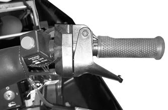
Checking/Adjusting Throttle Lever (Tension) NOTE: Ensure that the throttle cable is properly
seated in the throttle control housing.
1.Verify when releasing the throttle lever that the idle switch in the control housing is compressed. If the switch is not compressed the engine may be hard to start or will shut down when the throttle lever is released.
ZR-091
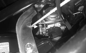
2.If the throttle cable needs to be adjusted, locate the throttle cable in-line adjuster next to the steering post. 3.Tighten nut against the in-line adjuster and cover the adjuster with rubber boot.
! WARNING
The throttle lever is intended to stop on handlebar before or at the same time as carburetor valve is at wide-open throttle (WOT) position. Damage may occur if throttle lever is adjusted so that it does not contact handle bar.
Carburetor (B-24)
REMOVING
1.Remove the screws securing the air cleaner cover to the air cleaner case and account for the filter and retaining plate.
ZR-143
2.Remove the flanged nuts securing the air cleaner assembly to the carburetor and engine. Account for the plate.
ZR-144

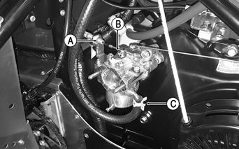
3.Remove the air cleaner case from the carburetor and engine. Account for the gasket. 4.Remove the nut (A) and screw (B) securing the choke cable to the carburetor; then remove the fuel hose (C) from the carburetor. Remove the carburetor from the engine.
ZR-145
5.Disconnect the rod from the carburetor; then remove the spring and hose from the governor arm.
ZR-145

6.Slide the carburetor off the mounting studs. Account for a gasket.
744-959A

1.Carefully remove the plastic cap from the idle fuel adjuster screw (A); then rotate the screw clockwise while noting the number of rotations (for assembling purposes) until lightly seated. Remove the screw.
2.Remove the pilot jet (B) from the carburetor. 3.Remove the cap screw (C) securing the float chamber to the carburetor; then remove the chamber and account for the rubber gasket. 4.Remove the float pin (D) securing the float (E) to the carburetor body; then remove the float and needle jet assembly (F). 5.Remove the main jet (G) and the nozzle (H) from the carburetor tower. CLEANING
1.Place all metallic components in a wire basket and submerge in carburetor cleaner. 2.Soak for approximately 30 minutes; then rinse with fresh parts-cleaning solvent. 3.Wash all non-metallic components with soap and water. Rinse thoroughly. 4.Dry all components with compressed air only making sure all holes, orifices, and channels are unobstructed. CAUTION
Do not force the idle fuel adjuster screw when rotating it clockwise; damage to the screw taper and carburetor orifice may result.
CAUTION
DO NOT place any non-metallic components in partscleaning solvent or carburetor cleaner because damage or deterioration will result.
5.Blow compressed air through all hoses to remove any obstructions. ! WARNING
Always wear safety glasses when drying components with compressed air.
CAUTION
DO NOT use wire or small drill bits to clean carburetor orifices, holes, or channels. Distorted or damaged orifices, holes, or channels can result in poor carburetor operation.
INSPECTING
1.Inspect the mixing body and jet orifices for cracks, nicks, stripped threads, and any other imperfections in the casting. 2.Inspect the float for perforations or damage. 3.Inspect the gaskets for distortion, tears, or noticeable damage. 4.When applicable, inspect the idle fuel adjuster screw, needle jet assembly, and pilot jet for wear, damage, or distortion. 5.Inspect the nozzle and main jet for obstructions or damage. 6.Inspect the carburetor insulator for damage, cracks, and tightness.
7.Place the carburetor insulator on a surface plate covered with #400 grit wet-or-dry sandpaper. Move the insulator over the surface plate using a figure-eight motion. The motion should produce an even wear pattern over the entire sealing area.
CAUTION
An air leak between the carburetor and engine will cause a lean condition and poor engine performance.
CAUTION
Water or parts-cleaning solvent must be used in conjunction with the wet-or-dry sandpaper or damage to the sealing surfaces may result.
8.Inspect the condition of the throttle return spring. CHECKING FLOAT HEIGHT
1.Remove the cap screw securing the float chamber; then remove the float chamber from the carburetor and account for the rubber gasket. 2.With the carburetor in an upside-down position, lift the float so the tip of the float lightly contacts the float arm; then measure the float height from the body of the carburetor and underside of the float.
Measurement should be 0.63”.

IO108
CAUTION
Do not bend the float in an attempt to adjust the height. Correct float height is obtained by replacing the needle jet assembly and/or the float.
ASSEMBLING
744-959A
1.Install the nozzle (H) and main jet (G) into the carburetor tower. 2.Place the needle jet assembly (F) and the float (E) into position and secure to the carburetor body with the float pin (D). 3.Secure the float chamber w/rubber gasket to the carburetor with the cap screw (C). 4.Install the pilot jet (B). 5.Install the idle fuel adjuster screw (A) and rotate the screw clockwise until lightly seated; then rotate the screw counterclockwise the proper number of rotations as noted during disassembling. Install the plastic cap.
CAUTION
Do not force the idle fuel adjuster screw when rotating it clockwise; damage to the screw taper and carburetor orifice may result.
1.Install the gasket; then with the governor rod installed on the carburetor, place the carburetor into position on the mounting studs. 2.Install the fuel supply hose on the carburetor using the clamp.
ZR-168
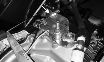
3.Pull the choke cable knob out completely; then hold the butterfly closed in the carburetor. Tighten the set screw to 6 in.-lb.
ZR-169
4.Place the gasket, air cleaner assembly, and plate into position on the carburetor; then secure with the flanged nuts. Tighten to 96 in.-lb.

ZR-144
5.Secure the air cleaner cover to the air cleaner with the screws. Tighten to 30-36 in.-lb.

ZR-143
6.Adjust the carburetor (see ADJUSTING sub-section). ADJUSTING The carburetor has been calibrated for average riding conditions; however, altitude, temperature, and general wear may necessitate certain carburetor adjustments. Since carburetor adjustments critically affect engine performance, two external adjustments can be made on the carburetor. These are the throttle stop screw and throttle cable.
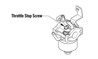
744-921Y
Throttle Stop Screw This screw controls the seating position of the throttle valve which in turn determines the proper idle speed. Rotate the screw clockwise to increase engine idle speed and counterclockwise to decrease engine idle speed.
Throttle Cable
REMOVING AND INSPECTING
1.Compress the throttle lever to the WOT position; then using a small pliers, remove the throttle cable from the lever. 2.Remove the C-clip securing the throttle cable to the control; then remove the throttle cable. 3.Cut the cable ties securing the throttle cable to the steering post. NOTE: Note the location of the cable tie for assem-
bly.
4.Rotate the throttle cable lever of the governor control arm to the wide-open position and route the cable end out of the arm; then loosen the throttle cable jam nuts and remove the throttle cable.

ZR-164
5.Inspect the throttle cable for damage or fraying. INSTALLING
1.Route the throttle cable through the slot in the throttle control and insert the cable end into the throttle control. Secure the cable with a C-clip. 2.Seat the drum into its lever recess; then secure the lever with a pin and push nut. 3.Place the throttle cable into the throttle cable bracket and secure with jam nuts. 4.Slide the end of the throttle cable into the throttle cable lever. 5.Secure the throttle cable to the steering post with a cable tie; then install the handlebar pad. 6.Open and close the throttle lever to make sure of no binding or sticking. ADJUSTING NOTE: Ensure that the throttle cable is properly
seated in the throttle control housing.
1.Verify when releasing the throttle lever that the round switch in the control housing is compressed. If the switch is not compressed the engine will shut down when the throttle lever is released.
ZR-089A

ZR-090
2.If the throttle cable needs to be adjusted, locate the throttle cable in-line adjuster next to the steering post; then adjust the in-line adjuster until the governor arm (A) starts to move.
ZR-090A
3.Tighten nut against the in-line adjuster and cover the adjuster with rubber boot.