13 minute read
Electrical System

Troubleshooting Fuel System
Problem: Carburetor Too Rich (0-1/4 Opening) Condition Remedy
1. Choke valve will not seat 1.Adjust — service — replace choke cable — assembly 2. Idle fuel adjuster screw out of adjustment 2.Adjust idle fuel adjuster screw 3. Float/needle jet obstructed — damaged — adjusted incor- 3.Remove obstruction — replace needle jet — float rectly 4. Pilot jet loose 4.Tighten pilot jet
Problem: Carburetor Too Rich (1/4-3/4 Opening) Condition Remedy
1. Pilot jet too large 1.Replace pilot jet 2. Float/needle jet obstructed — damaged — adjusted incor- 2.Remove obstruction — replace needle jet — float rectly 3. Main jet loose — too large 3.Tighten — replace main jet 4. Primary air passage obstructed 4.Remove obstruction
Problem: Carburetor Too Rich (3/4-WOT Opening) Condition Remedy
1. Main jet loose — too large 1.Tighten — replace with smaller main jet 2. Float/needle jet obstructed — damaged — adjusted incor- 2.Remove obstruction — replace needle jet — float rectly
Problem: Carburetor Too Lean (0-1/4 Opening) Condition Remedy
1. Choke valve hanging open 1.Adjust — service choke cable — valve assembly 2. Pilot jet — outlet obstructed 2.Remove obstruction 3. Float/needle jet obstructed — damaged — adjusted incor- 3.Remove obstruction — replace needle jet — float rectly
Problem: Carburetor Too Lean (1/4-3/4 Opening) Condition
Remedy
1. Pilot jet — outlet — main jet obstructed 2. Float/needle jet obstructed — damaged — adjusted incorrectly 1.Remove obstruction 2.Remove obstruction — replace needle jet — float
Problem: Carburetor Too Lean (3/4-WOT Opening) Condition Remedy
1. Main jet obstructed — too small 1.Remove obstruction — replace with larger main jet 2. Float/needle jet obstructed — damaged — adjusted incor- 2.Remove obstruction — replace needle jet — float rectly
Problem: General Fuel System (Engine Cuts Out at High RPM) Condition Remedy
1. Fuel delivery inadequate 1.Repair — replace hose 2. In-line fuel filter obstructed — damaged 2.Remove obstruction — replace in-line fuel filter 3. Gasoline contaminated 3.Replace gasoline — de-ice — clean carburetor 4. Gas-tank vent — hose obstructed 4.Remove obstruction — replace vent — hose
Electrical System
TESTING COMPONENTS Following are testing procedures for specific electrical components. All tests of the electrical components should be made using the digital Fluke Model 88 Multimeter. Replace any component that does not have a test value within specifications. NOTE: Whenever using a digital-style tester, “open
(infinite resistance)” denotes an overload and the meter reading will be OL since the meter is not calibrated to register resistance values of that magnitude.
NOTE: Always check the appropriate fuse before
testing a component for failure.
Transistorized Ignition System
The transistorized ignition system has no contact points. Therefore, this ignition system does not require periodic reconditioning of contact point surfaces or point gap adjustment. As a result, a strong spark is produced even at low speeds so maximum reliability can be ensured. OPERATION
GEN-0008
When the recoil starter handle is pulled, the flywheel is turned. An electromotive force generated in the primary winding of the ignition coil makes the transistor (TR1) conduct through the resistor (R) and forms the primary circuit (indicated by dashed lines). As the flywheel turns faster, the primary current increases, and the terminal voltage of the circuit consisting of the resistor (R) and the transistor (TR1) increases. This increases the working voltage at the connection of the series circuit (r1 + r2) connected in parallel to the primary circuit. As the flywheel turns further, the terminal voltage of the resistor (r2) in the resistor circuit (r1 + r2) rises to the level of working voltage of the transistor (TR2) when the ignition timing approaches the rated RPM, and, thus, the transistor (TR2) is turned on. As a result, the base current of (TR1) flowing through the resistor (R) is by-passed, and the transistor (TR1) is turned off from the conductive state. The current flowing through the primary winding (2) is thus interrupted, and rapid change occurs in the magnetic flux across the ignition coil. The result is a high surge voltage in the secondary winding (3). SPARK ADVANCE CHARACTERISTIC As noted above, the unit circuit detects a voltage and makes switching to produce a high voltage required to produce a spark. On the other hand, the wave form of the voltage generated in the primary winding changes as the flywheel turns. The working voltage (VS) of the unit circuit is at level A when the engine is started, but as the engine speed increases, the wave form of the voltage changes and advances to level B.
GEN-0009
TROUBLESHOOTING 1.Remove the spark plug and visually check its condition. Replace if fouled. Adjust spark plug gap to 0.028-0.031”. Attach the high tension lead to the spark plug and ground the plug on the cylinder head. NOTE: Make sure the emergency stop switch is in
the ON (UP) position, the ignition switch is in the RUN position, and the tether cord is connected to the tether switch.
2.Crank the engine over and check for a spark. If no spark is present, disconnect the main wiring harness from the engine. Crank the engine over. If spark is now present, the problem is either one or more of the following items:
A.Defective ignition switch
B.Defective emergency stop switch
C.Defective wiring harness
D.Defective tether switch
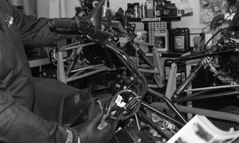
Testing Ignition Switches (Wiring Harness)
1.Disconnect the engine wires from the main wiring harness. 2.At the main wiring harness engine connector, connect the red tester lead to the violet wire; then connect the black tester lead to the engine ground (black wire).
3.With the ignition switch in the RUN position, the emergency stop switch in the ON position, and the tether cord connected, the meter must read no resistance. If the meter reads resistance, disconnect the ignition switch from the main wiring harness. If the meter now reads no resistance, replace the ignition switch.
725-704A
4.If the meter continues to read resistance with the ignition switch disconnected, disconnect the emergency stop switch. If the meter now reads no resistance, replace the emergency stop switch. 5.If the meter continues to read resistance with both the ignition switch and the emergency stop switch disconnected, disconnect the wires to the tether switch. If the meter now reads no resistance, replace the tether switch. 6.If the meter continues to read resistance with all three switches disconnected, replace the main wiring harness.
Testing Electrical Resistances
NOTE: The following test procedure starts by test-
ing the resistance for the spark plug cap and working back to the stator under the flywheel. Replace any component that does not have a test value within specifications.
SPARK PLUG CAP 1.Remove the spark plug cap from the high tension lead by rotating it counterclockwise. 2.Set the selector in the OHMS position. 3.Connect one tester lead to one end of the cap and the other tester lead to other end of the cap.
B170
4.Spark plug cap resistance must be between 40006000 ohms. MAGNETO 1.Disconnect the two white wires from the main harness. 2.Set the meter selector to the OHMS position; then connect the red and black tester leads to each of the two white wires. 3.The meter must show less than 1 ohm. EXTERNAL COIL Primary 1.Disconnect the single black/white wire lead of the coil from the main harness. 2.Set the meter selector to the OHMS position; then connect the red tester lead to the black/white wire and the black tester lead to the metal post of the coil. 3.Resistance must be within 11.25-11.75k ohms. Secondary 1.Remove the spark plug end cap from the high tension lead of the coil. 2.Set the meter selector to the OHMS position; then connect the red lead of the tester to the high tension lead to the coil and the black tester lead to ground. 3.Resistance must be within 6000-7000 ohms. LIGHTING COIL 1. Disconnect the two yellow wires from the main wiring harness. 2.Set the selector to the OHMS position. 3.Connect the tester leads to the two yellow leads on the engine-side connectors. 4.Lighting coil resistance must be between 0.46-0.68 ohm.
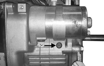
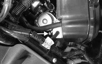
Testing Idle Switch
1.Disconnect the idle switch connector coming out from the front throttle control housing; then connect the ohmmeter leads to the red wire and black wire. 2.With the throttle lever in the idle position, the meter must read OL (infinite resistance). If the meter reads less than 1000 ohms, verify the switch is being compressed by the throttle lever by putting pressure on the end of the throttle lever in the direction of the arrow.
ZR-170
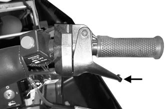
3.If the meter now reads OL (infinite resistance) with pressure on the throttle, the throttle cable will need to be adjusted. Refer to the throttle cable section in the service manual. If the meter still reads less than 1000 ohms, replace the front throttle control assembly. 4.Move the throttle lever to the wide-open position.
The meter must read less than 1 ohm. If the meter reads OL (infinite resistance), replace the front throttle control assembly.
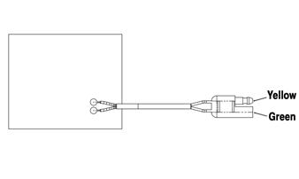
Testing Handlebar Warmer Elements
NOTE: Resistance will vary due to temperature;
therefore, this test should be made at room temperature of 22° C (72° F).
1.Open the hood; then disconnect the handlebar warmer two-wire connector. 2.Connect one ohmmeter lead to the yellow lead; then connect the other ohmmeter lead to the green lead.
ONS-019
3.The meter must read 14.4 ± 10% ohms. 4.Replace any element measuring less than or more than the specified amount. 5.Repeat test for the other element; then connect the leads. Close and latch the hood.
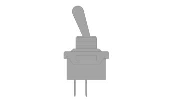
Testing Handlebar Warmer Switch
1.Open the hood; then disconnect the main harness wires from the switch. 2.With the handwarmer toggle in the OFF position, connect one ohmmeter lead to pin and the other ohmmeter lead to pin. The meter must read OL (infinite resistance).
ONS-018
3.With the handwarmer toggle in the ON position, connect one ohmmeter lead to pin and the other ohmmeter lead to pin. The meter must read 1 ohm or less resistance.
ONS-017
4.Connect the green/white wire to the bottom terminal and the brown wire to the top terminal on the switch.
Close and latch the hood.
Testing Headlight Switch
1.Open the hood; then disconnect the main harness wires from the switch. 2.With the headlight toggle in the HIGH BEAM position, connect one ohmmeter lead to pin and the other ohmmeter lead to pin. The meter must read 1 ohm or less resistance.

ONS-042
3.With the headlight toggle in the LOW BEAM, connect one ohmmeter lead to pin and the other ohmmeter lead to pin. The meter must read 1 ohm or less resistance. 4.Connect the white wire to the bottom terminal (LOW
BEAM), the yellow wire to the middle terminal and the blue wire to the top terminal (HIGH BEAM) on the switch. Close and latch the hood.

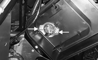
Testing Tether
NOTE: Resistance will vary due to temperature;
therefore, this test should be made at room temperature of 22° C (72° F).
1.Disconnect the two-wire connector from the tether switch. 2.Connect one ohmmeter lead to one pin; then connect the other ohmmeter lead to the other pin. 3.With the tether cord installed on the switch, the meter must read less than 1 ohm of resistance. With the tether cord removed from the switch, the meter must read OL (infinite resistance). NOTE: If the meter does not read as specified in
either test, the switch is defective and must be replaced.
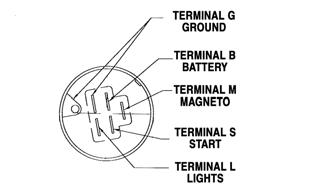
Testing Key Switch
ONS-119
1.Open the hood; then disconnect the main harness wires from the key switch. 2.With the key in the OFF position, connect one ohmmeter lead to Terminal G and the other ohmmeter lead to Terminal M. The meter must read 1 ohm or less resistance. 3.With the key in the ON position, connect one ohmmeter lead to Terminal G and the other ohmmeter lead to Terminal M. The meter must read more than 10,000 ohms. 4.With the key in the START position, connect one ohmmeter lead to Terminal G and the other ohmmeter lead to Terminal M. The meter must read more than 10,000 ohms. 5.With the key in the START position, connect one ohmmeter lead to Terminal B and the other ohmmeter lead to Terminal S. The meter must read 1 ohm or less resistance.
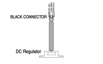
Testing DC Regulator
ONS-097
Checking DC power at the brake switch
1.Open the hood; then place the red lead on the red/ blue wire on the brake switch. 2.Place the black lead on the chassis ground located in front of the engine. DC voltage should be 12-14
VDC, pending electrical loads at engine idle RPM at room temperature. Checking AC voltage is present at the DC regulator connection 1.Disconnect the DC regulator from the main harness (black connector). 2.Set multimeter to AC voltage; then place the red lead on the yellow wire on the harness side of the DC regulator and the black lead on the black wire on the harness side of the DC regulator. 3.The meter should read approximately 14.5 VAC at engine idle RPM at room temperature.
Testing AC Regulator (with RPM Limiter)

ONS-098
1.Open the hood; then disconnect the handwarmer connectors from the main harness. 2.Insert red lead in the green wire and the black lead in the yellow wire. 3.The meter should read approximately 14.5 VAC at engine idle RPM with no accessories connected and at room temperature. Checking RPM Limiter 1.Ensure regulated AC voltage is present at the handwarmer connections and is within tolerance. 2.Disconnect the AC regulator/RPM limiter connector. 3.Set the multimeter to resistance; then insert the red lead on the purple wire on the harness side and the black lead on the engine ground. 4.The meter should read approximately 1.6 ohms at room temperature. If not, disconnect the connector for the ignition coil (located on the front of the engine). 5.With regulator/RPM limiter connector still disconnected, perform continuity check of the purple wire between the engine connector, and the regulator.
Should read continuity (0.2 ohms +/- 0.1 ohms). AC Regulator — No Output, No Headlights, No Hand Warmers 1.With the hand warmer switch in the ON position, verify there is no AC voltage at the hand warmer connectors (yellow and green wires). 2.Verify resistance at lighting coil of the stator by disconnecting the two bullet connectors (white wires) exiting the front of the engine. 3.With ohm setting on the meter selected, probe one of the two wires with the red lead and the other with the black lead. The resistance measurement should be 0.3 ohms ± 0.2 ohms at room temperature. 4.With the red lead in one of the connectors, and the black lead to the engine ground, resistance should be
“OL” (out of limits, open circuit). Insert the red lead in the other connector, keep the black on engine ground, the meter should read “OL”. 5.With lighting coil wires still disconnected, start engine, and allow to idle. With the meter set to AC voltage, meter should display 20-30 VAC at room temperature. 6.Check for continuity between the yellow wire at the lighting coil connection, and the yellow wire at the voltage regulator. 7.Check for continuity between the black wire at the stator and the black wire at the regulator. 8.Ensure all engine and chassis grounds are connected and tight.