11 minute read
General Information/Foreword

General Information/Foreword.........................................2
Snowmobile Identification.............................................2 Recommended Gasoline and Oil..................................3 Break-In Procedure......................................................3 Genuine Parts...............................................................3 Preparation for Storage................................................3 Preparation after Storage.............................................4 Torque Conversions (ft-lb/N-m)....................................4 Torque Specifications...................................................5 Engine Torque Diagram (B-25 Carburetor)..................6 Engine Torque Diagram (B-24 Carburetor)..................7 Engine Specifications...................................................8 Carburetor Specifications (B-25)..................................8 Carburetor Specifications (B-24)..................................9 Track Specifications.....................................................9 Front/Rear Shock Spring..............................................9 Rear Suspension Spring...............................................9 Front Shock Absorber...................................................9 Rear Shock Absorber...................................................9
Engine (B-25 Carburetor)................................................10
Removing....................................................................10 Disassembling............................................................12 Servicing Components................................................15 Assembling.................................................................22 Installing......................................................................25 Engine Oil...................................................................28 Recoil Starter..............................................................29 Troubleshooting Engine..............................................30
Engine (B-24 Carburetor)................................................31
Removing...................................................................31 Disassembling............................................................33 Servicing Components...............................................36 Assembling.................................................................42 Installing.....................................................................46 Engine Oil...................................................................50 Recoil Starter..............................................................50 Troubleshooting Engine..............................................52
Fuel System......................................................................53
Pre-Maintenance Checks...........................................53 In-Line Fuel Filter........................................................53 Carburetor (B-25).......................................................58 Carburetor (B-24).......................................................58 Throttle Cable.............................................................61 Troubleshooting Fuel System.....................................63
Electrical System..............................................................64
Transistorized Ignition System....................................64 Testing Ignition Switches (Wiring Harness).................64 Testing Electrical Resistances....................................65 Testing Idle Switch......................................................66 Testing Handlebar Warmer Elements.........................66 Testing Handlebar Warmer Switch..............................66 Testing Headlight Switch.............................................67 Testing Tether.............................................................67 Testing Key Switch......................................................67 Testing DC Regulator..................................................68 Testing AC Regulator (with RPM Limiter)...................68 Starter Relay Solenoid................................................69 Starter Motor...............................................................69
Drive Train/Track/Brake Systems...................................70
Drive Belt.....................................................................70 Drive Clutch.................................................................70 Driven Clutch...............................................................72 Drive Clutch/Driven Clutch..........................................73 Dropcase.....................................................................73 Track...........................................................................75 Brake System..............................................................77 Troubleshooting Track................................................80
Rear Suspension..............................................................81
Removing Skid Frame.................................................81 End Cap......................................................................81 Wear Strip...................................................................81 Rear Suspension Arm/Rear Springs...........................82 Rear Idler Wheels and Axle.........................................83 Slide Rail.....................................................................83 Installing Skid Frame...................................................85
Steering and Body............................................................86
Steering Post...............................................................86 Ski...............................................................................88 Ski Wear Bar...............................................................88 Tie Rods......................................................................88 Spindle........................................................................89 Ski Alignment..............................................................90 Front Suspension A-Arms...........................................90 Belly Pan.....................................................................92 Seat Assembly............................................................92 Gas Tank/Fuel Pump Assembly..................................93 Headlight Assembly....................................................94
Wiring Diagram.................................................................95
NOTE: Whenever a part is worn excessively,
cracked, or damaged in any way, replacement is necessary.
NOTE: Some illustrations and photographs used in
this manual are used for clarity purposes only and are not designed to depict actual conditions.
This Arctic Cat Service Manual contains service and maintenance information for the 2020 Arctic Cat ZR 200 Snowmobile. The manual is designed to aid service personnel in service-oriented applications. This manual is divided into sections. The sections cover specific snowmobile components or systems and, in addition to the standard service procedures, includes assembling, disassembling, and inspecting instructions. When using this manual as a guide, the technician should use discretion as to how much disassembly is needed to correct any given condition. This service manual is designed primarily for use by an Arctic Cat CatMaster Basic Level technician. The procedures found in this manual are of varying difficulty, and certain service procedures in this manual require one or more special tools to be completed. The technician should use sound judgment when determining which procedures can be completed based on their skill level and access to appropriate special tools. All Arctic Cat publications and snowmobile decals display the words Warning, Caution, and Note to emphasize important information. The symbol ! WARNING identifies personal safety-related information. Be sure to follow the directive because it deals with the possibility of severe personal injury or even death. A CAUTION identifies unsafe practices which may result in snowmobile-related damage. Follow the directive because it deals with the possibility of damaging part or parts of the snowmobile. The symbol NOTE: identifies supplementary information worthy of particular attention. At the time of publication, all information, photographs, and illustrations were technically correct. Some photographs and illustrations used in this manual are used for clarity purposes only and are not designed to depict actual conditions. Because Arctic Cat Inc. constantly refines and improves its products, no retroactive obligation is incurred. All materials and specifications are subject to change without notice. Keep this manual accessible in the shop area for reference. Product Service and Warranty Department Arctic Cat Inc.
SPECIAL TOOLS A number of special tools must be available to the technician when servicing this snowmobile.
Description p/n
V Blocks 0644-535 Surface Plate 0644-016 Shock Spring Removal Tool 0644-057 Fluke Model 88 Multimeter 0644-559
NOTE: Special tools are available from the Arctic
Cat Service Parts Department.
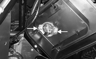
Snowmobile Identification
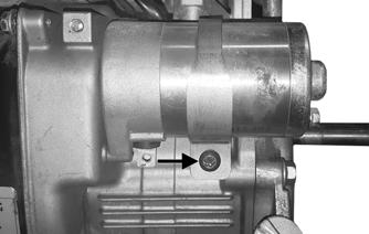
The Arctic Cat Snowmobile has two important identification numbers. The Vehicle Identification Number (VIN) is stamped into the tunnel near the right-side footrest. The Engine Serial Number (ESN) is on the front side of the recoil cover.
0726-200
ONS-263
These numbers are required to complete warranty claims properly. No warranty will be allowed by Arctic Cat Inc. if the engine serial number or VIN is removed or mutilated in any way.
Recommended Gasoline and Oil
RECOMMENDED GASOLINE
CAUTION
Do not use white gas or gasolines containing methanol. Only Arctic Cat approved gasoline additives should be used.
The recommended gasoline to use in these snowmobiles is 87 octane regular unleaded. NOTE: In many areas, oxygenates (either ethanol or
MTBE) are added to the gasoline. Oxygenated gasolines containing up to 10% ethanol or up to 15% MTBE are acceptable gasolines; however, whenever using oxygenated gasolines, the carburetor main jet must be one size larger than the main jet required for regular unleaded gasoline. For example, if a 77.5 main jet is recommended for regular unleaded gasoline, an 80 main jet must be installed if using an oxygenated gasoline.
When using ethanol-blended gasoline, adding a gasoline antifreeze is not necessary since ethanol will prevent the accumulation of moisture in the fuel system. RECOMMENDED OIL The recommended oil to use in the engine is 0W-40 synthetic oil. See the viscosity chart for details.
CAUTION
Any oil used in place of the recommended oil may cause serious engine damage.

OILCHARTJ
Break-In Procedure
The Arctic Cat engine requires a short break-in period (approximately 10 operating hours) before being subjected to heavy load conditions or full-throttle operation. Strict adherence to the break-in procedure will contribute to optimum performance and longevity of the engine. During break-in, a maximum of 1/2 throttle is recommended; however, brief full-throttle accelerations and variations in driving speeds contribute to good engine break-in. After the 10-hour break-in period, the snowmobile may be taken to an authorized Arctic Cat Snowmobile dealer for a checkup and oil change at the discretion and expense of the snowmobile owner.
Genuine Parts
When replacement of parts is necessary, use only genuine Arctic Cat parts. They are precision-made to ensure high quality and correct fit.
Preparation for Storage
Prior to storing the snowmobile, it is extremely important that it be properly serviced to prevent corrosion and component deterioration. Arctic Cat recommends the following procedure to prepare the snowmobile for storage. 1.Clean the seat cushion with vinyl protectant and a damp cloth. 2.Clean the snowmobile thoroughly by hosing dirt, oil, grass, and other foreign matter from the undercarriage, tunnel, hood, and belly pan. Allow the snowmobile to dry thoroughly. DO NOT get water into any part of the engine. 3.Drain all gas from the gas tank. Close the gas tank shut-off valve by rotating it clockwise; then drain the gasoline from the carburetor by loosening the drain screw on the carburetor float chamber. 4.Plug the muffler outlet with a clean cloth. 5.With the ignition key in the OFF position:
A.Disconnect the high tension wire from the spark plug; then remove the spark plug.
B.Pour 10 mL (approximately two teaspoons) of petroleum-based oil into the spark plug hole; then pull the recoil starter handle slowly about five times.
C.Install the spark plug and connect the high tension wire. 6.Change the oil. 7.Lubricate the rear suspension with a low-temperature grease. 8.Tighten all screws, nuts, and cap screws securely. 9.Make sure all rivets holding components together are tight. Replace all loose rivets.
CAUTION
Never crank the engine over without grounding the spark plug. Damage to the transistorized ignition may result.
10.Clean and polish the hood, console, and chassis with
Cat Cleaner (p/n 4639-371). DO NOT USE SOL-
VENTS. THE PROPELLANT WILL DAMAGE
THE FINISH. 11.If possible, store the snowmobile indoors. Raise the rear of the snowmobile off the floor and block up the rear end. Cover the snowmobile with a snowmobile cover to protect it from dirt and dust. 12.If the snowmobile must be stored outdoors, block the entire snowmobile off the ground and cover it with a snowmobile cover to protect it from dirt, dust, and rain.
CAUTION
Avoid using a plastic cover as moisture will collect on the snowmobile causing corrosion.
Preparation after Storage
Taking the snowmobile out of storage and correctly preparing it for operation will ensure many miles and hours of trouble-free snowmobiling. Arctic Cat recommends the following procedure to prepare the snowmobile. 1.Clean the snowmobile thoroughly. Polish the exterior of the snowmobile using the cleaner. 2.Clean the engine cooling fins and the recoil starter vents. Remove the cloth from the muffler. 3.Check all control wires and cables for signs of wear or fraying. Replace if necessary. Use cable ties or tape to route wires and cables away from hot or rotating parts. 4.If not done during preparation for storage, lubricate the rear suspension with a low-temperature grease. 5.Check brake-lever travel distance, all controls, ski alignment, track tension, track alignment, brake pads, and ski wear bars; adjust or replace as necessary. 6.Examine the in-line fuel filter and clean or replace if necessary. 7.Fill the gas tank. 8.Clean the seat cushion with the vinyl protectant. 9.Check the spark plug (clean, gap, and/or replace as necessary); then start the engine and ensure proper carburetor adjustments.
Torque Conversions (ft-lb/N-m)
ft-lb N-m ft-lb N-m ft-lb N-m ft-lb N-m 1 1.4 26 35.4 51 69.4 76 103.4 2 2.7 27 36.7 52 70.7 77 104.7 3 4.1 28 38.1 53 72.1 78 106.1 4 5.4 29 39.4 54 73.4 79 107.4 5 6.8 30 40.8 55 74.8 80 108.8 6 8.2 31 42.2 56 76.2 81 110.2 7 9.5 32 43.5 57 77.5 82 111.5 8 10.9 33 44.9 58 78.9 83 112.9 9 12.2 34 46.2 59 80.2 84 114.2 10 13.6 35 47.6 60 81.6 85 115.6 11 15 36 49 61 83 86 117 12 16.3 37 50.3 62 84.3 87 118.3 13 17.7 38 51.7 63 85.7 88 119.7 14 19 39 53 64 87 89 121 15 20.4 40 54.4 65 88.4 90 122.4 16 21.8 41 55.8 66 89.8 91 123.8 17 23.1 42 57.1 67 91.1 92 125.1 18 24.5 43 58.5 68 92.5 93 126.5 19 25.8 44 59.8 69 93.8 94 127.8 20 27.2 45 61.2 70 95.2 95 129.2 21 28.6 46 62.6 71 96.6 96 130.6 22 29.9 47 63.9 72 97.9 97 131.9 23 31.3 48 65.3 73 99.3 98 133.3 24 32.6 49 66.6 74 100.6 99 134.6 25 34 50 68 75 102 100 136
Torque Specifications
NOTE: Torque specifications have the following tol-
erances:
Torque (ft-lb) Tolerance
0-15 ±20% 16-39 ±15% 40+ ±10%
Item
Secured to Torque ft-lb DRIVE SYSTEM
Drive Clutch Engine 20 Driven Clutch Driven Shaft 40 Brake Bracket Bearing Holder Chassis 60 in.-lb Drop Case Sprocket Driveshaft 16 Drop Case Chassis 96 in.-lb Torque Bumper Bracket Chassis 16 Brake Caliper* Chassis 80 in.-lb Brake Disc* Brake Hub 48 in.-lb Brake Manifold Steering Support 72 in.-lb Brake Disc* Driveshaft 16 MC Mount Master Cylinder 30 in.-lb
STEERING/FRONT SUSPENSION/CHASSIS
Ski Spindle 16 Ski Wear Bar 50 in.-lb Ski Ski Handle 50 in.-lb Steering Post* Chassis 96 in.-lb Steering Tie Rod* Steering Post 20 Tie Rod* Spindle Arm 15 Steering Support Spar 96 in.-lb Steering Support Upper Console 96 in.-lb A-Arm Chassis 30 A-Arm Spindle 20 Shock Absorber Spindle 16 Shock Absorber Chassis 16
REAR SUSPENSION
Rail* Crossbrace Axle 20 Crossbrace Axle (Shock)* Rail 20 Support Bracket Rail 20 Support Bracket Front Arm 20 Rear Axle Housing* Rail 20 Rear Wheels Rear Axle Housing 34 Track Adjuster Rear Axle Housing 96 in.-lb Limiter Strap Limiter Strap 40 in.-lb End Cap Rail 45 in.-lb Wear Strip Rail 50 in.-lb
* w/Blue Loctite #243
Engine Torque Diagram (B-25 Carburetor)
NOTE: Before engine assembly, ensure all threaded areas are clean to ensure an accurate torque value is
achieved. Torque values have a range of ± 20%.
= Torque control required = Lubricate with Yamaha 4-Stroke Engine Oil
= Apply Loctite = Lubricate with Yamaha Snowmobile Grease
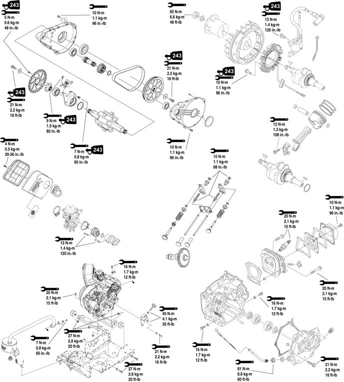
200-ENG-20-1
Engine Torque Diagram (B-24 Carburetor)
NOTE: Before engine assembly, ensure all threaded areas are clean to ensure an accurate torque value is
achieved.
= Torque control required
= Apply Loctite = Lubricate with Arctic Cat 4-Stroke Engine Oil
= Lubricate with Arctic Cat All-Temp Grease

200-ENG-19-1
Engine Model Number (w/B-25 Carburetor) 7DHJ Engine Model Number (w/B-24 Carburetor) 7D9A Displacement 192 cc No. of Cylinders 1 Bore x Stroke 70 x 50 mm Compression Ratio 8.4:1 Cooling System Air Spark Plug (NGK) BPR4ES Spark Plug Gap 0.028-0.031” Piston Skirt/Cylinder Clearance 0.0012-0.0018” Piston Pin Diameter 0.6297-0.6299” Piston Pin Bore Diameter (max) 0.6300” Piston Pin/Connecting Rod Small End Clearance 0.008-0.024” Piston Ring End Gap (1st/2nd) 0.008-0.016” (oil) 0.008-0.028” Piston Ring/Groove Clearance (1st) 0.0016-0.0031” (2nd) 0.0008-0.0024” Piston Ring Thickness (1st/2nd) 0.059” (oil) 0.098” Piston Diameter (10 mm from skirt edge) (min) 2.752” Cylinder/Head Distortion (max) 0.004” Connecting Rod Small End Bore Inside Diameter 0.6302-0.6307” Connecting Rod Big End Inside Diameter 1.1024-1.1030” Connecting Rod Big End Side Clearance 0.008-0.024” Cam Lobe Height 1.050-1.059” Crank Pin Diameter (min) 1.1011-1.1017” Crank Pin/Connecting Rod Clearance 0.0006-0.0018” Crankshaft Rod Journal (Out-of-Round/Taper) 0.004” Crankshaft Runout (t.i.r.) 0.0016” Valve Guide Inside Diameter (max) 0.22” Valve Guide/Stem Clearance (max) (Int) 0.0016-0.0024” (Exh) 0.0024-0.0031” Valve Face Width (min) 0.028” Valve Face Runout (max) 0.0012” Valve Clearance — Cold (59°-77° F) (Int/Exh) 0.004” Valve Seat Contact Width (min) (Int/Exh)0.067” Valve Stem Diameter (min) (Int/Exh)0.022” Valve Stem Runout (max) 0.0004” Valve Spring Free Length (max) 1.245” Camshaft End Running Surface (max) 0.592” Camshaft End Play (max) 0.002” Vibration — Hand/Arm 3.8 m/s Vibration — Seat < 0.5 m/s
Main Jet Pilot Jet Pilot Screw (Turns Out) Float Height
107.5 17.5 2 8 mm (0.31”)