9 minute read
Rear Suspension


ZR-098
NOTE: Do not allow either of the syringes to
bottom out. This could introduce air into the system.
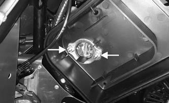
9.Apply light pressure to the syringe on the caliper and remove the syringe from the fitting. Place a rag under the caliper in your hand and remove the bleed fitting.
Quickly replace the bleed plug. Tighten to 12 in.-lb. 10.Clean any excess brake fluid from the caliper using isopropyl alcohol.
ZR-099
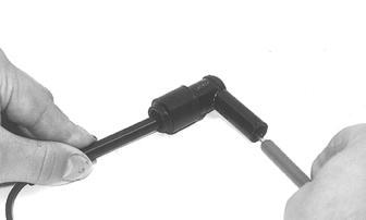
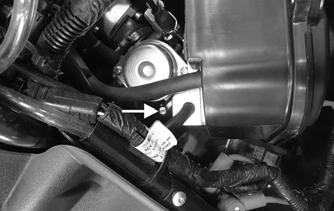
11.With the master cylinder still in the downward position, apply light pressure to the syringe before removing the syringe from the fitting. Remove the bleed fitting. Quickly replace the bleed port screw.
Tighten to 12 in.-lb. Clean any excess brake fluid from the caliper using isopropyl alcohol. 12.With the bleed block still in the caliper, squeeze on the lever to verify proper brake feel. If the desired feel has been attained, the master cylinder can be positioned to the desired location and secured. 13.Remove the bleed block and install the brake pads and the clip; then secure the pads using the pin.
Spread to secure.


ZR-100
14.Position the brake caliper in its location on the disc and loosely secure at this time leaving them loose enough to allow the caliper to move. 15.Squeeze the brake lever. This will center the caliper on the disc. Tighten the cap screws to 80 in-lb.
Release the brake lever and verify that the caliper is centered over the disc. If the caliper is not centered, adjust the mounting location as needed. 16.Install the gas tank and the console/seat; then close and secure the hood.
Troubleshooting Track
Problem: Track Edge Frayed — Drive Lugs Worn Condition Remedy
1. Track alignment adjusted incorrectly 1.Align — replace track
Problem: Track Worn Adjacent to Outer Drive Lugs Condition Remedy
1. Track tension adjusted incorrectly 1.Adjust track tension 2. Rear idler wheels dirty — damaged 2.Clean — replace idler wheels
Problem: Track Ratchets — Slaps Tunnel Condition Remedy
1. Track tension adjusted incorrectly (too loose) 1.Adjust track tension (tighten) 2. Drive sprockets misaligned — damaged 2.Align — replace sprockets
Problem: Wear-Strip Wear Excessive Condition Remedy
1. Slide rail bent — broken — damaged 1.Repair — replace slide rail 2. Track alignment adjusted incorrectly 2.Adjust track alignment
Rear Suspension
REAR ARM SPRING TENSION The rear spring tension is adjusted for the weight of the driver. Three possible adjustments exist. 1st block position — light operator 2nd block position — medium operator 3rd block position — heavy operator This section has been organized so each procedure can be completed individually and efficiently. The technician should use discretion and sound judgment when removing and installing components.
Removing Skid Frame
1.Place a support stand under the rear bumper; then remove the two cap screws securing the upper idler wheel assembly to the tunnel. 2.Remove the cap screws securing the rear arm upper axle to the tunnel; then remove the two cap screws securing the rear shock axle to the tunnel.

ZR-118
3.Raise the rear of the snowmobile high enough to allow the skid frame assembly to drop out from the tunnel. Remove the skid frame assembly.
End Cap
REMOVING
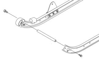
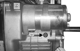
1.Remove the lock nut, washers, and cap screw securing the end cap.

SNO-973
2.Using a hammer, tap the end cap off the rail. CLEANING AND INSPECTING
1.Inspect the end cap area of the slide rail for cracks and wear. 2.Inspect the end cap for any signs of cracking or wear. 3.Clean both the slide rail area and the end cap. Using compressed air, clean the areas of dirt and gravel.
4.Inspect the cap screw for cracked, stretched, or damaged threads. Use a new lock nut when assembling. INSTALLING
1.Position the end cap on the slide rail; then align the hole in the end cap with the hole in the slide rail. 2.Secure with a cap screws, washers, and new lock nut.
Tighten to 80 in.-lb.
! WARNING
Always wear safety glasses when using compressed air.
Wear Strip
REMOVING NOTE: Prior to removing the wear strips, inspect
each wear strip for wear. The wear strip must be 0.42" thick or thicker. If the wear strip measurement is less than specified, replacement of both wear strips is necessary.
1.With the skid frame removed, remove the machine screw and lock nut securing the wear strip to the front of the slide rail.

SNO-978
2.Align the wear strip with the openings (windows) in the track; then using a suitable driving tool, drive the wear strip rearward off the slide rail. CLEANING AND INSPECTING
1.Clean the slide rail using parts-cleaning solvent and compressed air.
2.Inspect the slide rail for cracks. If any cracks are found, replace the slide rail. 3.Using a straightedge, inspect the slide rail for any unusual bends. Place the straightedge along the bottom surface of the slide rail. If the rail is found to be bent, it must be replaced. 4.Place the straightedge along the side of the slide rail.
If rail is found to be bent, it must be replaced. INSTALLING NOTE: Use a file to remove any sharp edges on the
lower portion of the rail.
1.Align the wear strip with the openings (windows) in the track and from the back, start the wear strip onto the rail; then using a block of wood and a hammer, drive the wear strip forward into position. 2.Secure with a machine screw and lock nut. Tighten to 50 in.-lb. ! WARNING
Always wear safety glasses while using compressed air.

Rear Suspension Arm/Rear Springs
DISASSEMBLING
1.With the skid frame removed, remove the cap screws securing the rear arm to the support bracket and rail; then remove the rear arm. Account for and note the location of all hardware. 2.Remove the rear springs and sleeves from the rear arm.

ONS-001
3.Remove the cap screws securing the rear spring assembly to the rails; then remove the retaining rings securing the upper idler wheels to the axle. Remove the wheels, spacers, and washers. Remove the shock.
ONS-002
INSPECTING
1.Inspect all rear arm weldments for cracks or unusual bends. 2.Inspect all tubing for cracks or unusual bends. 3.Inspect the axles for wear or damage. 4.Inspect the upper and lower bearings for wear or damage. 5.Inspect the two spring adjuster blocks for damage. 6.Inspect the springs for excessive wear, cracks, or imperfections. ASSEMBLING
1.Apply a light coat of grease to the axles and the bushing areas. 2.Install the axles into the rear shock assembly; then install the washers and spacers over the axles. 3.Install the upper idler wheels onto the upper axle and secure using the retaining rings.
ONS-002
4.Apply a light coat of grease to the axles and the bushing areas. 5.Place the rear arm into position on the support bracket and rail; then secure with cap screws (threads coated with blue Loctite #243). Tighten to 20 ft-lb.
ONS-001
Rear Idler Wheels and Axle

744-844A
DISASSEMBLING
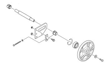
1.With the skid frame removed, remove the cap screws and flat washers securing the outer idler wheels.
Remove the idler wheels from the axle and account for the adjuster bushings. 2.Slide the axle out of the rear axle housing and the rear spacer.
1.Clean the bearings with a clean cloth. 2.Inspect all idler wheel bearings. Rotate each bearing (by hand) and if any roughness or binding is noted, replace the idler wheel assembly. 3.Inspect the outer rubber portion of the idler wheels for cracks and poor bonding. 4.Inspect the plastic hub of each idler wheel for cracking. 5.Inspect the axle for wear and damaged threads. Damaged threads may be repaired with a 3/8 x 16 tap. ASSEMBLING
1.In order, slide the axle through the rear axle housing; then place a spacer on the axle. Slide the axle through the opposite axle housing. 2.Place the adjuster bushings on the axle (on the outside of each axle housing). Make sure the adjuster bushing is positioned properly toward the adjusting cap screw. 3.Place the rear idler wheels on the axle and secure with two cap screws (coated with blue Loctite #243) and washers. Tighten to 20 ft-lb.
Slide Rail
744-844A

SNO-994
REMOVING NOTE: When replacing one or both slide rails is
necessary, remove one slide rail at a time. The remaining slide rail will then hold the crossbraces and brackets in their correct assembly order which is much quicker than to completely disassemble the entire skid frame.
1.With the skid frame removed, remove the cap screw, washers, and lock nut securing the end cap to the slide rail. Remove the end cap from the slide rail.
SNO-973
2.Remove the cap screw securing the cross-brace axle to the slide rail.

SNO-974
3.Remove the cap screw securing the rear suspension arm to the support bracket. 4.Remove the cap screws and lock nuts securing the rear suspension arm support bracket.

SNO-975
5.Remove the cap screw and washer securing the rear idler wheel to the axle. Slide the wheel off the axle and account for the adjuster bushing. 6.Remove the two cap screws and lock nuts securing the rear axle housing; then remove the housing. 7.Remove the push nuts and solid rivets securing the shock pads to the slide rail. Remove the shock pads.
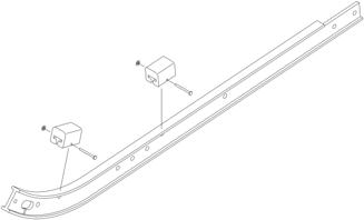
SNO-995
8.Remove the slide rail from the skid frame. INSPECTING
1.Inspect the slide rail for cracks or unusual bends. 2.Inspect the wear strip for wear. The wear strip must be 0.42” thick or thicker. If the wear strip measurement is less than specified, replacement of both wear strips is necessary.
INSTALLING
1.Install the rear axle housing and adjuster bushing; then secure with cap screws and lock nuts. Tighten to 20 ft-lb. 2.Install the rear idler wheel and secure the rear idler wheel with a cap screw (coated with blue Loctite #243) and washer. Tighten to 20 ft-lb. 3.Secure the rear suspension arm support bracket to the slide rail with cap screws and lock nuts. Tighten to 20 ft-lb.
SNO-975
4.Secure the rear arm to the support bracket with the cap screw. Tighten to 20 ft-lb.