18 minute read
sDrive Train/Track/Brake System

Starter Relay Solenoid
TESTING 1.Disconnect the solenoid connector from the main wiring harness. 2.Place the ohmmeter leads across the solenoid coil terminals. The ohmmeter must read 3-5 ohms.
NOTE: An in-line ammeter would measure between
2 and 4 amps of solenoid coil current flow with the battery connected.
CAUTION
NEVER connect an in-line ammeter with the large starter cables because the 200 amps of current flow will instantly damage most ammeters.
Starter Motor
REMOVING NOTE: The engine must be removed from the chas-
sis in order to remove the starter motor.
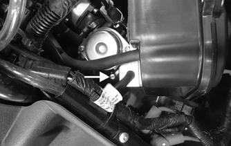
1.Remove the screw securing the starter motor strap to the crankcase.
ZR-262
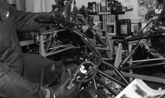
2.Remove the cap screws securing the recoil and the magneto cover. 3.Remove the two cap screws securing the starter motor to the crankcase. Remove the starter motor. TESTING STARTER MOTOR NOTE: Before installing the starter motor, perform
test to ensure proper operation using the following procedure.
1.Attach a black jumper cable to a good ground on the starter. 2.Attach the opposite end of the black jumper cable to the negative post of a good 12-volt battery. 3.Attach the red jumper cable to the positive post of the battery. 4.Holding the starter firmly down on a work bench, touch the red jumper cable to the positive cable stud of the starter.
! WARNING
Be sure to keep clear of the pinion gear area as it will spin at a high RPM when the red jumper cable is touched to the positive stud. Personal injury may result if contact is made with the spinning pinion gear.
INSTALLING 1.Secure the starter motor using the two cap screws.
Tighten to 11 N-m, 1.1 kg-m (8 ft-lb).
ZR-261
2.Secure the starter motor strap to the crankcase using the existing screw (threads coated with blue Loctite #243). Tighten to 11 N-m, 1.1 kg-m (8 ft-lb).
ZR-262
Drive Train/Track/Brake Systems
This section has been organized into sub-sections for servicing drive train, track, and brake systems; however, some components may vary from model to model. The technician should use discretion and sound judgment when removing and installing components. NOTE: Whenever a part is worn excessively,
cracked, or damaged in any way, replacement is necessary.
SPECIAL TOOLS A number of special tools must be available to the technician when servicing the drive train, track, and brake systems.

Description p/n
Clutch Alignment Bar 0644-624 Drive Clutch Retention Tool 0644-644 Engine Alignment Tool 0644-643
NOTE: Special tools are available from the Arctic
Cat Service Parts Department.
Drive Belt

REMOVING
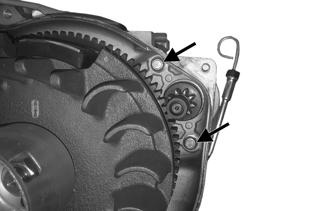
1.Set the brake lever lock; then open the hood. 2.Remove the screws securing the clutch guard; then remove the guard.
ZR-148
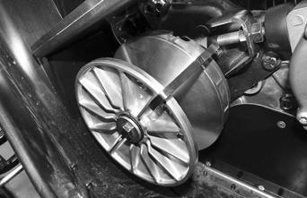
3.While pulling up on the drive belt between the clutches, rotate the driven clutch to help the driven clutch open.
ZR-126
4.Remove the drive belt by pulling it up and over the sheave. INSTALLING
1.Place the belt (so the part number can be read) between the sheaves of the driven clutch; then rotate the driven clutch to help the driven clutch open.
ZR-127
2.With the sheaves apart, roll the belt over the drive clutch. 3.Release the brake lever lock, and roll the belt back and forth to allow the driven clutch sheaves to fully close. 4.After the belt is installed properly, secure the clutch guard using the existing screws. Tighten to 30 in.-lb. 5.Close and latch the hood.
Drive Clutch
CHANGING ROLLERS/SPRING Removing 1.Install the drive clutch retention tool over the drive clutch sheaves; then remove the cap screw washer securing the drive clutch to the crankshaft. Account for a spacer on the crankshaft.
ZR-125
Disassembling 1.While holding the clutch sheaves together; remove the retention tool from the clutch. 2.Remove the movable sheave from the stationary sheave; then remove the spring. 3.Remove the movable sheave cover and the six roller weights. Account for the three sliders.

ONS-004
NOTE: The idler bearing is not serviceable. If the
bearing is defective, the drive clutch will have to be replaced.
Cleaning and Inspecting 1.Using parts-cleaning solvent, wash grease, dirt, and foreign matter off all components; dry with compressed air.
! WARNING
Always wear safety glasses when using compressed air to dry components.
2.Remove any drive belt dust accumulation from the stationary sheave, movable sheave, and bushings using parts-cleaning solvent only. 3.Inspect stationary sheave, movable sheave, and cover for cracks or imperfections in the casting. 4.Inspect the spring for distortion, cracks, or wear. 5.Inspect roller weights for damage or wear (flat spots). 6.Inspect sliders for damage or wear.
Assembling 1.Starting at the top of the movable sheave, install the rollers with the painted side to the right and continue around the sheave adding all six rollers in the same orientation.

ONS-036
NOTE: Available roller weight kits from Arctic Cat
are p/n 0646-987 (18g — Blue), p/n 0646-988 (14g — Red) and p/n 0646-989 (10g — Black).
2.Install the four sliders into the cover; then install the cover onto the movable sheave.

ONS-037
3.Install the spring onto the stationary sheave; then install the movable sheave over the stationary sheave and secure using the drive clutch retention too. Installing 1.Install the spacer onto the crankshaft; then install the drive clutch assembly onto the shaft. 2.Secure using the cap screw and washer. Tighten to 20 ft-lb.
3.Check alignment between the drive clutch and driven clutch. 4.Install the drive belt.
CAUTION
When installing the drive clutch, do not tighten the cap screw with any kind of impact tool. Tighten cap screw using a hand torque wrench only. Failure to do so could result in sheave damage.
Never operate the engine without the belt guard/access panel secured.
5.Start the engine and let the engine idle for 1-2 minutes; then shut the engine off and torque the cap screw again to 20 ft-lb.
Driven Clutch
REMOVING
1.Open the hood; then remove the drive belt. 2.Remove the cap screw and washer securing the driven clutch. Remove the driven clutch from the driven shaft. DISASSEMBLING
1. Compress the clutch by pressing down on the driven clam; then while holding down the cam, remove the snap ring securing the driven cam.

ZR-121
2.Remove the driven cam and the spring. CLEANING AND INSPECTING
1.Using parts-cleaning solvent, wash grease, drive belt dust, and foreign matter off all components.
2.Inspect the rollers for damage, cracks, or wear. 3.Inspect the sheaves for any gouges, cracks, or other damage. Also, inspect threaded areas of sheaves for damaged or stripped threads. 4.Inspect the driven cam for cracks or damage. The ramp portions of the cam must be free of gouges and damage.
5.Inspect spring for distortion, crystallization, or breaks. 6.Inspect the driven cam and movable sheave bearings for wear. If wear is present, replace the bracket or sheave. REPLACING ROLLERS
1.With the driven cam removed, remove the roller screws securing the rollers in the movable sheave.
CAUTION
Do not use steel wool or a wire brush to clean driven clutch components. A wire brush or steel wool will cause the sheaves to be gouged (thus, the drive belt may not slide properly between sheaves). Decreased performance and possible accelerated drive belt wear will result.

ZR-122
2.Place a new roller into position and secure with the existing roller screws. Tighten to 8 ft-lb. ASSEMBLING NOTE: The driven spring rate will increase 1 to 3
and A to C. Increasing driven spring rate will slow up shift and speed up back shift.
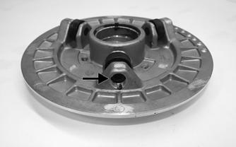
1.Install the spring into the sheave making sure the tab is placed into notch (C). 2.Install the driven cam over the spring making sure the spring tab is installed into notch (2).
ZR-124
3.Press down on the driven cam and install the key aligning the stationary sheave and the cam. Secure the cam using the existing snap ring making sure the snap ring is installed into the groove in the top of the cam.
3.To move the driven clutch outward on the shaft, add alignment washers to the driven shaft. NOTE: Available shim washers from Arctic Cat are
p/n 0648-835 (0.039 in.) and (p/n 0648-836 (0.020 in.).
4.Arrange washers to obtain the correct offset; then install driven clutch and belt and secure using the cap screw and washer. Tighten to 40 ft-lb. 5. Install the belt, close and latch the hood.
ZR-121
INSTALLING
1.Set the brake lever lock. 2.With the existing shims installed on the driven shaft, install the driven clutch onto the driven shaft. Secure using the existing cap screw and washer. Tighten to 40 ft-lb. 3.Install the drive belt; then check drive clutch/driven clutch alignment.
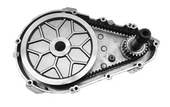
Dropcase
REMOVING NOTE: The engine and skid frame assemblies will
have to be removed in order to remove the dropcase from the chassis.
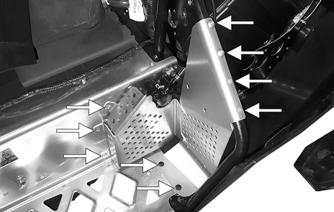
1.Remove the rivets securing the left-side footrest to the chassis; then remove the footrest.
Drive Clutch/Driven Clutch
If premature drive belt wear is experienced or if drive belt turns over, check offset. Also, offset must be checked whenever either drive clutch or driven clutch is serviced. To check offset, use appropriate Clutch Alignment Bar. Checking offset 1.Open the hood; then remove the clutch guard and the drive belt. 2.Place Alignment Bar onto the back side of the driven clutch and the front side of the drive clutch. The bar should be flat against both clutches.

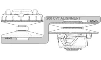
SNO-993
Correcting Offset 1.Remove the cap screw and washer securing the driven clutch to the driven shaft; then remove the driven clutch. 2.To move the stationary sheave inward on the shaft, remove alignment washers located on driven shaft.
ZR-152
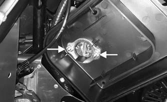
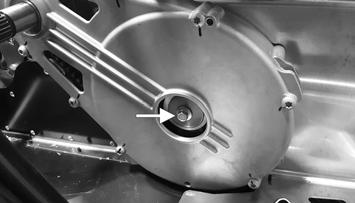
2.Remove the plastic plug from the dropcase; then remove the cap screw and washer securing the dropcase to the driveshaft.

ZR-151
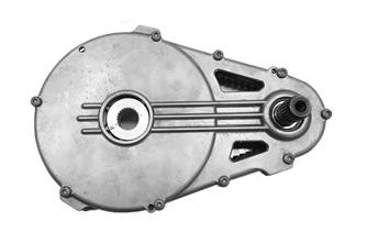
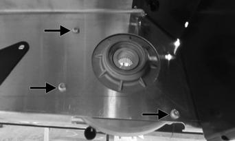
3.Remove the five screws securing the dropcase to the tunnel; then remove the dropcase from the chassis.

ZR-149


ZR-150
DISASSEMBLING NOTE: The bearings within the dropcase and the
dropcase cover are not serviceable. If a bearing is damaged, the cover or case assemblies will have to be replaced.
1.Remove the screws securing the dropcase cover to the dropcase; then remove the cover. Account for two alignment pins.
ZR-155
4.Place the dropcase downward bracing only the case and not the lower pulley; then apply heat to the case around the lower pulley. 5.Using a suitable press or an adequate press tool, press the lower pulley from the bearing. ASSEMBLING NOTE: The bearings within the dropcase and the
dropcase cover are not serviceable. If a bearing is damaged, the cover or case assemblies will have to be replaced.
1.With the bearing clean and free of debris, press the lower pulley into the lower dropcase bearing making sure it is fully pressed into the bearing. 2.With the bearing clean and free of debris, position the driven shaft into the upper dropcase bearing.

ZR-153
2.Remove the belt from the upper pulley; then carefully remove the belt. 3.Remove the thrust washer and the upper pulley from the driven shaft; then remove the driven shaft from the upper bearing.
ZR-156
3.Position the upper pulley onto the driven shaft; then install the thrust washer onto the pulley. Install the belt over the lower pulley and then over the upper pulley.
ZR-154
4.Install the dropcase cover and secure using the existing screws. Tighten to 10 ft-lb using a crisscross pattern.
ZR-153
INSTALLING
1.Position the dropcase assembly over the driveshaft and aligning with the mounting locations in the chassis. 2.Secure the dropcase assembly to the tunnel using the existing screws. Tighten to 96 in.-lb.
ZR-149 ZR-150

3.Secure the dropcase to the driveshaft using the existing cap screw and washer. Tighten to 16 ft-lb.
ZR-151
4.Install the plastic plug over hole in the dropcase. 5.Install the skid frame assembly and the engine.
Track
TRACK TENSION NOTE: Track tension and track alignment are
interrelated; therefore, always check both, even if only one adjustment seems necessary.
Track tension is directly related to the overall performance of the snowmobile. If the track is too loose, it may slap against the tunnel causing wear, or it may ratchet on the track drive sprockets. Arctic Cat recommends that the track tension be checked once a month and adjusted accordingly.
! WARNING
Track tension must be properly maintained. Personal injury could result if a track is allowed to become excessively loose.
Checking Track Tension ! WARNING
DO NOT attempt to check or adjust track tension with engine running. Turn ignition key to the OFF position. Personal injury could result from contact with a rotating track.
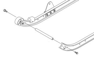
2.At the lower mounting position of the rear shock, hook a spring scale around a track clip; then pull down on the scale to 9 kg (20 lb). Measure the deflection (distance) between the bottom of the wear strip and the running surface of the track clip. The measurement should be 50 mm (2 in.).
SNO-950

Adjusting Track Tension 1.Loosen the idler wheel cap screws. 2.Loosen the rear idler wheel adjusting bolt jam nuts.
SNO-949

NOTE: To ensure proper track tension adjustment,
perform all adjustments on both sides of the snowmobile.
3.If the deflection (distance between the bottom of the wear strip and the inside of the track) exceeds specifications, tighten the adjusting bolts to take up excessive slack in the track. 4.If the distance between the bottom of the wear strip and the inside surface of the track is less than specified, loosen the adjusting bolts to increase the slack in the track. 5.Check track alignment. 6.When proper track tension is obtained, tighten the adjusting bolt jam nuts against the axle housings. 7.Tighten idler wheel cap screws to 34 ft-lb. NOTE: Since track tension and track alignment are
interrelated, always check both even if only one adjustment seems necessary.
! WARNING
If jam nuts are not tightened properly, the adjusting bolts could loosen causing the track to become extremely loose and, under some operating conditions, allow the idler wheels to climb over the track lugs forcing the track against the tunnel causing the track to “lock.” If a track “locks” during operation, severe personal injury could result.
TRACK ALIGNMENT Proper track alignment is obtained when the outside of the rear idler wheels are equal distance from the edge of the track. Excessive wear to the idler wheels, drive lugs, and track will occur if the track is improperly aligned. Arctic Cat recommends that the track alignment be checked once a week or whenever the track tension is adjusted. Checking Track Alignment
1.Position the tips of the skis against a wall; then using a shielded safety stand, raise the rear of the snowmobile off the floor making sure the track is free to rotate.
2.Start the engine and accelerate slightly. Use only enough throttle to turn the track several revolutions.
SHUT ENGINE OFF.
! WARNING
Make sure the ignition key is in the OFF position and the track is not rotating before checking or adjusting track alignment. Personal injury could result if contact is made with a rotating track.
! WARNING
The tips of the skis must be positioned against a wall or similar object for safety.
NOTE: Allow the track to coast to a stop. DO NOT
apply the brake because it could produce an inaccurate alignment condition.
3.When the track stops rotating, check the relationship of the idler wheels and the edge of the track. If the distance from the rear idler wheels to the edge of the track is the same on both sides, no adjustment is necessary. 4.If the distances from the idler wheels to the edge of the track are not the same on both sides, an adjustment is necessary. Adjusting Track Alignment 1.On the side of the track which has the edge of the track furthest to the outside of the rear idler wheel, loosen the idler wheel cap screw and the adjusting bolt jam nut; then rotate the adjusting bolt clockwise 1 to 1 1/2 turns.

SNO-949
2.Check track alignment and continue adjustment until proper alignment is obtained. NOTE: Make sure correct track tension is main-
tained after adjusting track alignment (see TRACK TENSION section).
3.After proper track alignment is obtained, tighten both the adjusting bolt jam nut and the idler wheel cap screw securely. ! WARNING
If a jam nut is not tightened properly, the adjusting bolt could loosen causing the track to become dangerously loose.
Brake System
REMOVING AND INSPECTING
1.Remove the screw securing the brake lever assembly to the handlebar. Remove the assembly.


ONS-024
2.Remove the screws, rivets, and washers securing the brake disc guard and the right-side footrest to the chassis; then remove them as an assembly.
ZR-157
3.Remove the two screws securing the brake caliper assembly
ZR-158
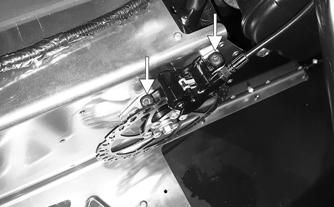
4.Remove the cap screw and washer securing the brake disk assembly to the driveshaft; then remove the brake disc.
ZR-160
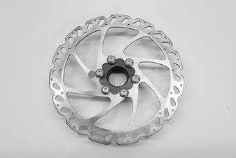
5.Remove the six screws securing the brake disc to the brake hub.
ZR-159
NOTE: If the hub assembly needs to be removed,
remove the skid frame; then remove the screws securing the hub to the tunnel.
INSTALLING NOTE: If the hub assembly was removed, secure it
to the tunnel using the existing screws. Tighten to 60 in.-lb.
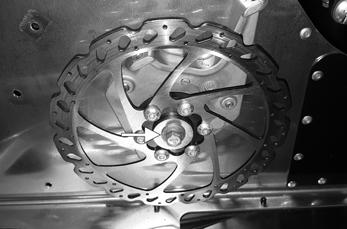
1.Secure the brake disc to the brake hub using the existing screws. Tighten to 48 in.-lb.
ZR-158
5.Secure the footrest and brake disc guard to the chassis using new rivets, washers, and the existing screws.
ZR-159

2.Position the brake disc assembly onto the driveshaft; then secure the assembly to the shaft using the existing cap screw and washer (threads coated with blue
Loctite #243). Tighten to 16 ft-lb.
ZR-160
3.Position the brake caliper in its location on the disc and loosely secure at this time leaving them loose enough to allow the caliper to move. 4.Squeeze the brake lever. This will center the caliper on the disc. Tighten the cap screws (threads coated with blue Loctite #243) to 80 in-lb. Release the brake lever and verify that the caliper is centered over the disc. If the caliper is not centered, adjust the mounting location as needed.
ZR-157
6.Position the brake lever assembly onto the handlebar and secure using the exiting screw. Tighten securely.
ONS-024
Bleeding the Brake System NOTE: A video of the bleed procedure has been cre-
ated by Hayes: https://www.youtube.com/watch?v=bAsO35FWvpg
NOTE: During the bleed process, always keep the
brake caliper below the master cylinder.
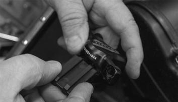
1.Open the hood; remove the four screws securing the console/seat assembly and slide the console/seat rearward and out of the way. 2.Remove the pin securing the brake pads; then remove the pads. Account for the brake pad clip.

ZR-101
3.Insert the bleed block (included with the bleed kit) into the caliper. This will hold the pistons in place.
ZR-094
4.Loosen the screw securing the master cylinder to the handlebar; then rotate it downward.


ZR-095
5.Attach the appropriate fittings to the syringes; then fill the syringe that will be installed into the master cylinder 1/4 full of DOT 4 or 5 brake fluid. Fill the other syringe 3/4 full.
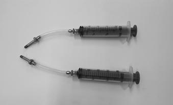
ZR-102
NOTE: Purge all air from the syringes and fittings
before proceeding.
6.With the caliper below the master cylinder, remove the bleed port screw from the master cylinder and attach the syringe.
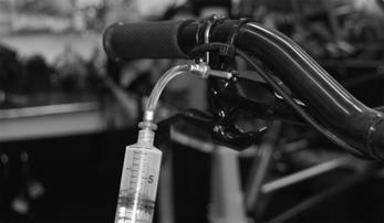
ZR-096
7.Remove the bleed port screw from the caliper and attach the other syringe (that is 3/4 full).
ZR-097
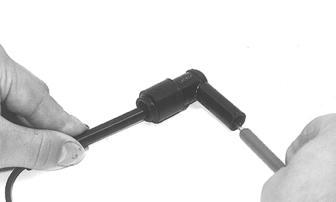
8.While holding a syringe in each hand and in a vertical position, apply pressure to the caliper syringe while pulling back the master cylinder syringe.
Reverse the process several times until air is no longer in the system.