TROUBLESHOOTING
Electrical Systems All tests of the electrical components should be made using the digital Fluke Model 77 Multimeter. Replace any component that does not have a test value within specifications. NOTE: Whenever using a digital-style tester, “open (infinite resistance)” denotes an overload and the meter reading will be OL since the meter is not calibrated to register resistance values of that magnitude. NOTE: Always check the appropriate fuse before testing a component for failure. NOTE: Whenever a part is worn excessively,
cracked, or damaged in any way, replacement is necessary. SPECIAL TOOLS
A number of special tools must be available to the technician when servicing the electrical systems. Description
p/n
CATT II
0544-023
Arctic Cat Diagnostic System Manual
2256-974
Laptop Diagnostic Tool
0744-048
Actuator Test Harness
0644-518
Fluke Model 77 Multimeter
0644-559
MaxiClips
0744-041
Throttle Position Sensor (TPS) Adjustment Tool Kit
3639-891
NOTE: Special tools are available from the Arctic Cat Service Parts Department.
1. Remove the spark plugs and visually check their condition. Replace any fouled plug. Attach the spark plugs to the high tension leads and ground them to the engine.
CAUTION Before checking for spark, place all the engine switches in the deactivated position. In the event the engine could be flooded, engage the starter several times to clear the engine of excess fuel.
CAUTION Never crank the engine over without grounding the spark plugs. Damage to coils and/or CDI/ECM may result.
NOTE: Make sure the ignition switch and the emergency stop switch are in the ON position.
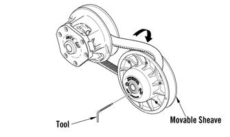
2. Crank the engine over and check for spark. If no spark is present, check to make sure the throttle cable is properly tensioned. Compress the throttle control and while holding the throttle control in this position, crank the engine over and check for spark. If spark is now present, adjust the throttle cable tension. TESTING Throttle Control Switch
1. Disconnect the handlebar harness connector; then connect the red meter lead to the yellow wire; then connect the black meter lead to the black wire. 2. With the throttle lever in the idle position, the meter must read less than 1 ohm. If the meter reads OL (infinite resistance), replace the control assembly.
Ignition System
3. Move the throttle lever to the wide open position. The meter must read OL (infinite resistance). If the meter reads less than 1000 ohms, replace the control assembly.
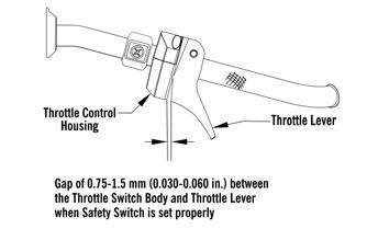
NOTE: There must be 0.75-1.5 mm (0.030-0.060 in.)
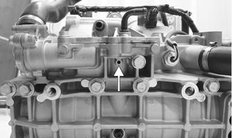
Throttle Position Sensor
free-play between the throttle lever and the control housing.
NOTE: Two-stroke engines equipped with a throttle position sensor have a protective feature called “fail-safe” ignition timing preventing engine damage should the TPS fail. If the TPS does fail, the engine may run normally at low RPM but will run poorly at high RPM allowing the operator to get the snowmobile to safety with no engine damage. The engine will continue to operate this way until the TPS is adjusted or replaced. CHECKING TPS
0752-478
NOTE: If the snowmobile is in warranty, breaking the seal on the idle screw jam nut or the Phillips-head screws on the TPS will void warranty. If the TPS is tested out of specification, the throttle body must be replaced. If the snowmobile is out of warranty, proceed to ADJUSTING TPS. NOTE: The TPS should only be checked using the CATT II Tool.
93