40 minute read
Steering and Body


This section has been organized into sub-sections for servicing steering and body components; however, some components may vary from model to model. The technician should use discretion and sound judgment when removing and installing components. NOTE: Whenever a part is worn excessively,
cracked, or damaged in any way, replacement is necessary.
SPECIAL TOOLS A number of special tools must be available to the technician when servicing the steering and body systems.
Description
Handlebar Stand Steering Post Stand
p/n
5639-152
5639-946
NOTE: Special tools are available from the Arctic
Cat Service Parts Department.
Steering Post (ZR/XF/Pantera/Norseman)
REMOVING 1.Rotate the two quarter turns to the vertical position; then pull the top of the side panel out and up and off the skid plate. 2.Remove the Torx screw securing the front of the hood to the chassis; then loosen the two quarter turns securing the hood.
0752-484
3.Disconnect the hood harness and remove the hood.
4.Disconnect the exhaust temperature sensor from the main harness; then remove all springs securing the expansion chamber. Remove the expansion chamber. 5.Remove the push rivets securing the right-side steering boot to the chassis. This allows access to the two nuts securing the bottom of the steering post.
SNO-763
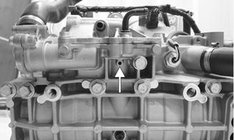
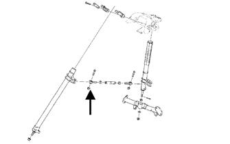
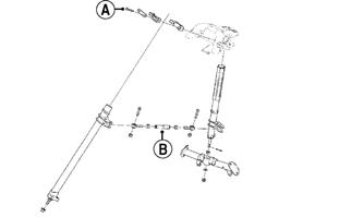
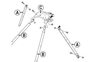
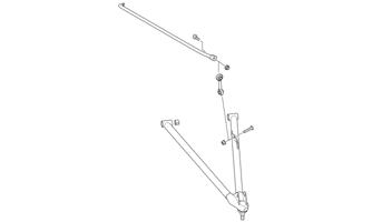
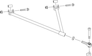
6.Remove the nut (A) securing the bottom of the existing steering post to the steering stop bracket; then remove the nut (B) securing the steering tie rod assembly to the steering post. Discard both nuts.
SNO-2221A
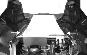
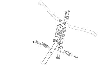
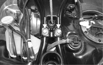
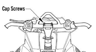
7.Remove the cap screws and handlebar caps securing the handlebar to the top of the handlebar riser; then remove the two nuts securing the top of steering post to the chassis. Account for both steering post blocks and retaining plate.
SNO-357
8.Carefully remove the steering post from the snowmobile.
INSTALLING 1.Install steering post into position and secure to the steering stop bracket with a new M10 nut. Be sure to
align the steering post ball joint alignment tab
with the steering stop bracket. Tighten to 43 ft-lb.
SNO-2218
2.Secure the tie rod assembly to the steering post using a new M10 nut. Be sure to align the tie rod ball joint alignment tab with the steering post. Tighten to 35 ft-lb.
SNO-2219
3.Secure the right-side steering boot to the chassis using the existing push rivets.
SNO-763
4.Secure the top of the steering post to the steering support using the existing retaining plate and nuts.
Tighten to 96 in.-lb. 5.Install the handlebar riser and handlebar to the top of the steering post and secure using the existing caps and screws. Tighten evenly to 15 ft-lb.
SNO-357
6.Install the expansion chamber using the existing springs; then connect the exhaust temperature sensor to the main harness.
7.Position the hood onto the snowmobile and connect the hood harness connector.
8.Secure the hood with the six Torx-head screws and tighten securely. 9.Install the access panels onto the lower console; then close the access panels. 10.Install three cable ties to secure the handlebar harness to the riser block.
NOTE: Do not secure the brakeline hose with the
lower cable tie.
NOTE: Make sure when securing the harness or hoses
to the riser that all cable tie locks are directed inward.
746-214A
CAUTION
With the handlebar secured and the cable installed, check maximum right/left turning capabilities to ensure that the throttle cables, brakeline hose, and harness wires are routed so they do not become pinched or stretched.
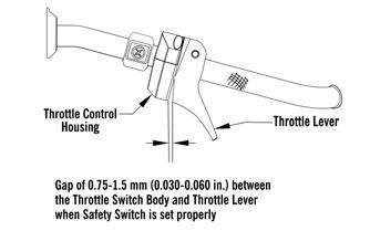
NOTE: After installing and adjusting the handlebar, ver-
ify that the throttle lever free-play is within specification.
Steering Post (XF HC)
REMOVING 1.Rotate the two quarter turns to the vertical position; then pull the top of the side panel out and up and off the skid plate. 2.Remove the Torx screw securing the front of the hood to the chassis; then loosen the two quarter turns securing the hood.
0752-484
3.Disconnect the hood harness and remove the hood.
4.Disconnect the exhaust temperature sensor from the main harness; then remove all springs securing the expansion chamber. Remove the expansion chamber. 5.Remove the push rivets securing the right-side steering boot to the chassis. This allows access to the two nuts securing the bottom of the steering post.
SNO-763
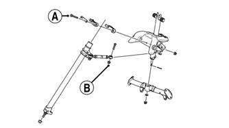
6.Remove the nut (A) securing the bottom of the existing steering post to the steering stop bracket; then remove the nut (B) securing the steering tie rod assembly to the steering post. Discard both nuts.
SNO-2221A
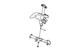
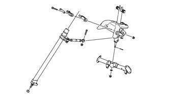
7.Remove the Torx-head screw and nut securing the tie rod link to the secondary steering post; then remove the two machine screws and nuts securing the top of the secondary steering post to the chassis. Account for both steering post blocks and retaining plate.
SNO-2226B
8.Carefully remove the secondary steering post from the snowmobile.
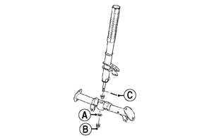
9.Remove and discard the cotter pin (C) and nyloc nut (B) securing the steering post to the lower steering support bracket. Account for a thrust washer (A).

SNO-2225A
10.Remove the two cap screws securing the existing steering support (C) to the front spar tubes (B); then remove the two cap screws securing the steering support to the side support tubes (A). Retain all cap screws and nuts.
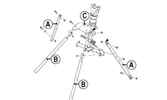
SNO-2227A
11.Remove the two cap screws securing the rear portion of the steering support to the rear spar tubes.
XM212A
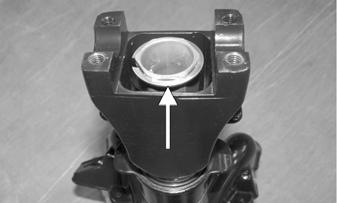
12.With the telescoping steering assembly removed from the snowmobile; press down on the adjusting block until the inner snap ring is exposed. Remove the snap ring.
SNO-739A
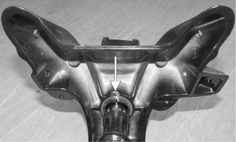
13.Remove the retaining ring securing the bottom side of the steering post; then remove the post from the steering support. Account for two bearings.
SNO-740A
INSPECTING 1.Inspect all welded areas for cracks or deterioration. 2.Inspect the steering post and steering-post retaining plate for cracks, bends, or wear. 3.Inspect the adjuster caps and mounting block for cracks or wear.
INSTALLING 1.Insert the telescoping steering post into the steering support along with two bushings; then secure the steering post using the existing retaining ring.
SNO-740A
NOTE: Verify the bushings are properly oriented
(the seam should be centered front to back).
2.Install the adjusting block onto the steering post and secure using the existing snap ring.
SNO-739A
3.Install the steering post assembly onto the front and rear spar tubes and into the thrust washer (A) and the lower steering post support. Secure with a new nyloc nut (B) and a new cotter pin (C). Tighten to 20 ft-lb and spread the cotter pin to secure.
SNO-2225A
4.Secure the steering support to the front and rear spar tubes using the existing cap screws. Tighten to 25 ft-lb.
5.Install the secondary steering post into position and secure to the steering stop bracket with a new M10 nut. Be sure to align the steering post ball joint
alignment tab with the steering stop bracket.
Tighten to 43 ft-lb.
SNO-2218
6.Secure the tie rod assembly to the steering post using a new M10 nut. Be sure to align the tie rod ball joint alignment tab with the steering post. Tighten to 35 ft-lb.
SNO-2219
7.Secure the right-side steering boot to the chassis using the existing push rivets.
SNO-763
8.Secure the top of the steering post to the steering support using the existing retaining plate and new nuts (A). Tighten to 96 in.-lb.
SNO-2226A
9.Connect the tie rod (B) from the adjustable steering post to the secondary steering post using the machine screw and nut. Tighten to 20 ft-lb. 10.Install the expansion chamber using the existing springs; then connect the exhaust temperature sensor to the main harness.
11.Position the handlebar to the desired position; then secure using the existing cap and all eight screws.
Tighten evenly to 15 ft-lb.
0747-617
12.Install the upper and lower console; then install the gas tank and seat using the existing hardware. 13.Install the hood and both access panels. 14.Install the push-mount cable ties on the handlebar harness into the handlebar riser.
0749-029

CAUTION
With the handlebar secured and the cable installed, check maximum right/left turning capabilities to ensure that the throttle cables, brakeline hose, and harness wires are routed so they do not become pinched or stretched.
NOTE: After installing and adjusting the handle-
bar, verify that the throttle lever free-play is within specification.
Steering Post (M)
REMOVING 1.Rotate the two quarter turns to the vertical position; then pull the top of the side panel out and slide the panel forward. Remove the panel. 2.Remove the Torx screw securing the front of the hood to the chassis; then loosen the two quarter turns securing the hood.
0752-484
3.Disconnect the hood harness and remove the hood.
4.Disconnect the exhaust temperature sensor from the main harness; then remove all springs securing the expansion chamber. Remove the expansion chamber. 5.Remove the push rivets securing the right-side steering boot to the chassis. This allows access to the two nuts securing the bottom of the steering post.
SNO-763
6.Remove the nut (A) securing the bottom of the existing steering post to the steering stop bracket; then remove the nut (B) securing the steering tie rod assembly to the steering post. Discard both nuts.
SNO-2221A
7.Remove the Torx-head screw and nut (B) securing the tie rod link to the secondary steering post; then remove the two machine screws (A) and nuts securing the top of the secondary steering post to the chassis. Account for both steering post blocks and retaining plate.
SNO-346A
8.Carefully remove the secondary steering post from the snowmobile.
9.Tie the recoil rope in a loose knot to prevent the rope from going into the recoil; then remove the recoil handle from the recoil rope. 10.Remove the eight machine screws and caps securing the handlebar and riser to the fixed steering post assembly.
INSTALLING 1.Position steering post assembly over the spar tubes, both side supports and into the lower steering support; then secure the assembly using existing cap screws and nuts. Tighten cap screws to 23 ft-lb.
0747-883

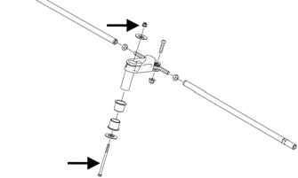
11.Remove and discard the cotter pin securing the fixed steering post; then remove and discard the lock nut but retain the thrust washer.
SNO-334
2.Secure the bottom of the steering post to the lower steering support using existing thrust washer and new nyloc nut. Tighten to 20 ft-lb. Install Cotter Pin into steering post and spread to secure.
SNO-333
12.Remove the cap screws securing the existing steering support (C) to the spar tubes (B); then remove the two cap screws securing the steering support to the side support tubes (A). Retain all cap screws but discard all nuts.
SNO-333
3.Install the secondary steering post into position and secure to the steering stop bracket with a new M10 nut. Be sure to align the steering post ball joint
alignment tab with the steering stop bracket.
Tighten to 43 ft-lb.
SNO-2218
INSPECTING 1.Inspect all welded areas for cracks or deterioration. 2.Inspect the steering post and steering-post retaining plate for cracks, bends, or wear. 3.Inspect the adjuster caps and mounting block for cracks or wear.
SNO-2218
4.Secure the tie rod assembly to the steering post using a new M10 nut. Be sure to align the tie rod ball joint alignment tab with the steering post. Tighten to 35 ft-lb.
SNO-2219
5.Secure the right-side steering boot to the chassis using the existing push rivets.
SNO-763
6.Route the recoil rope behind the lower steering support and up through the new steering support and through the existing recoil handle. Tighten rope in a knot.
7.Secure the top of the secondary steering post to the steering support using the existing steering post blocks, machine screws and nuts. Tighten to 8 ft-lb. 8.Connect the tie rod from the secondary steering post to the fixed steering post using existing machine screw and new nyloc nut. Tighten to 20 ft-lb.
SNO-346
9.Connect the tie rod (B) from the adjustable steering post to the secondary steering post using the machine screw and nut. Tighten to 20 ft-lb. 10.Install the expansion chamber using the existing springs; then connect the exhaust temperature sensor to the main harness. 11.Position the handlebar to the desired position; then secure using the existing cap and all eight screws.
Tighten evenly to 15 ft-lb.
0747-883
12.Install the hood and both access panels. 13.Install three cable ties to secure the handlebar harness to the riser block.
NOTE: Also secure the brakeline hose with the lower
cable tie.
NOTE: Make sure when securing the harness or hoses to the
riser that all cable tie locks are directed inward.
0746-219
CAUTION
With the handlebar secured and the cable installed, check maximum right/left turning capabilities to ensure that the throttle cables, brakeline hose, and harness wires are routed so they do not become pinched or stretched.
NOTE: After installing and adjusting the handle-
bar, verify that the throttle lever free-play is within specification.
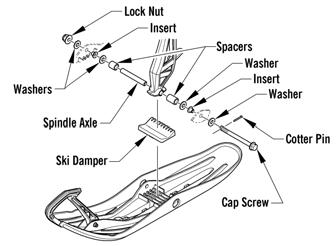
Ski (ZR/XF/Pantera)
REMOVING 1.Elevate the front of the snowmobile and secure on a support stand. 2.Remove and discard the cotter pin; then remove the nut and cap screw securing the ski to the spindle. NOTE: Note the orientation of the damper for
installation purposes.
INSPECTING 1.Inspect the ski for cracks or deterioration. 2.Inspect the ski for abnormal bends or cracks. 3.Inspect the wear bar for wear. 4.Inspect all hardware and the spindle bushings for wear and damage. 5.Inspect the rubber damper for damage or wear.
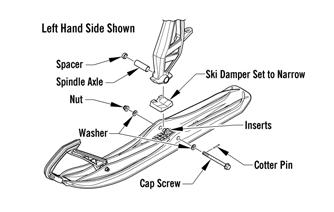
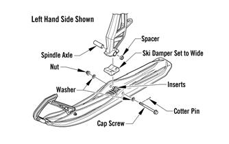
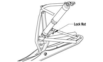
INSTALLING 1.Slide a washer onto the cap screw used to secure the ski; then apply low-temperature grease to the shaft portion of the cap screw and spindle axle. 2.Install the spindle axle into the spindle; then position the ski damper into the bottom of the ski making sure the damper is properly positioned for the desired ski stance.
0746-796
0746-797
NOTE: The ski damper must be positioned in the
ski so it is directly under the spindle.
3.With the cap screw hole of the ski centered with the spindle axle, slide the cap screw with washer through the outside of the ski and spindle assemblies. NOTE: Local laws and/or regulations regarding
maximum width of the ski stance may be applicable. Always comply with the maximum width laws and/or regulations when adjusting ski stance.
NOTE: Install the cap screw so the lock nut will be
located to the inside of the ski and the cotter pin slot in the cap screw will be horizontal with the ski.
4.Install the remaining washer and lock nut; then tighten the lock nut to 35 ft-lb. NOTE: Ensure that the cotter pin slot in the cap
screw is still horizontal with the ski.
5.Install a new cotter pin from the back side of the ski cap screw and spread the pin.
Ski (Norseman)
REMOVING 1.Elevate the front of the snowmobile and secure on a support stand. 2.Remove and discard the cotter pin; then remove the nut and cap screw securing the ski to the spindle. 3.Remove the ski. Account for the rubber damper and washers.
INSPECTING 1.Inspect the ski for cracks or deterioration. 2.Inspect the ski for abnormal bends or cracks. 3.Inspect the wear bar for wear. 4.Inspect all hardware and the spindle bushings for wear and damage. 5.Inspect the rubber damper for damage or wear.
INSTALLING NOTE: Before installing the skis, make sure the car-
bide of the split wear bar will be installed toward the inside of the ski when installed on the snowmobile.
1.Slide a washer onto the ski cap screw; then apply low-temperature grease to the cap screw shaft and spindle axle.
0748-981
2.Install the spindle axle into the spindle; then position the ski damper into the ski grooves making sure the grooved side of the damper is installed rearward. 3.Install the spacers and washers onto the spindle axle as follows:
Minimum ski stance (both on the inside of the spindle) Maximum ski stance (both on the outside of the spindle) 4.With the cap screw hole of the ski centered with the spindle axle, slide the cap screw with washer through the outside of the ski.
NOTE: Local laws and/or regulations as to maxi-
mum width of the ski stance may be applicable. Always comply with the maximum width laws and/or regulations when adjusting ski stance.
NOTE: Install the cap screw so the lock nut will be
located to the inside of the ski and the cotter pin slot in the cap screw will be horizontal with the ski.
5.Install the remaining washers and lock nut; then tighten the lock nut to 35 ft-lb. Ensure the cotter pin slot in the cap screw is still horizontal with the ski. 6.Install the cotter pin from the back side of the ski cap screw and spread the pin. Repeat for opposite ski.
Ski (XF HC/M)
REMOVING 1.Elevate the front of the snowmobile and secure on a support stand. 2.Remove and discard the cotter pin; then remove the nut and cap screw securing the ski to the spindle. NOTE: Note the orientation of the damper for
installation purposes.
3.Remove the ski. Account for the rubber damper, axle, spacers and washers.
INSPECTING 1.Inspect the ski for cracks or deterioration. 2.Inspect the ski for abnormal bends or cracks. 3.Inspect the wear bar for wear. 4.Inspect all hardware and the spindle bushings for wear and damage. 5.Inspect the rubber damper for damage or wear.
INSTALLING 1.Slide a washer onto the cap screw used to secure the ski; then apply low-temperature grease to the shaft portion of the cap screw and spindle axle. 2.Install the spindle axle and spacers into the spindle; then position the ski damper into the bottom of the ski making sure the damper is properly positioned for the desired ski stance.
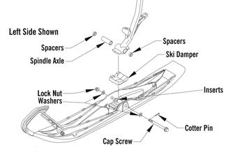
0752-477
NOTE: The ski damper must be positioned in the
ski so it is directly under the spindle.
3.With the cap screw hole of the ski centered with the spindle axle, slide the cap screw with washer through the outside of the ski and spindle assemblies. NOTE: Install the cap screw so the lock nut will be
located to the inside of the ski and the cotter pin slot in the cap screw will be horizontal with the ski.
4.Install the remaining washer and lock nut; then tighten the lock nut to 35 ft-lb. 5.Install a new cotter pin from the back side of the ski cap screw and spread the pin.
Ski Wear Bar
The ski wear bar is a replaceable bar attached to the underside of the ski. If the snowmobile is operated primarily in deep snow, ski wear bar wear will be minimal; however, if the snowmobile is operated on terrain where the snow cover is minimal, the ski wear bar will wear faster. Arctic Cat recommends that the ski wear bars be replaced if worn to 1/2 of original diameter.
REMOVING 1.Raise the front of the snowmobile and secure with a suitable stand.
2.Remove the lock nuts securing the wear bar to the ski; then remove the wear bar.
INSTALLING 1.Install the wear bar into the ski making sure it is fully seated using a rubber mallet. 2.Secure the wear bar with lock nuts. Tighten to 96 in.-lb.
Spindle (ZR/XF/Pantera/Norseman)
0747-904
REMOVING 1.Position the front of the snowmobile on a safety stand; then remove the ski. 2.Remove the cap screws and lock nuts securing the shock absorber. Account for two axles.
3.Remove the lock nut securing the tie rod to the spindle arm. Account for the washer on the top side. 4.Remove the two lock nuts securing the spindle to the upper and lower A-arms; then using a rubber mallet, remove the arms from the spindle. 5.Remove the spindle.
INSPECTING 1.Inspect the spindle for excessive wear, cracks, bends, or imperfections. 2.Inspect the A-arm bushings and axle area for wear. 3.Inspect the ski spindle axle and bearings for wear, damage, or loose fit. Replace the bearings as a set. NOTE: Replacing the ski bolt bushings is difficult. The
existing bushings will be damaged during removal. Be careful, however, not to damage the spindle when removing the bushings. Press the new bushings into the spindle.
INSTALLING 1.Place the shock absorber into position. Secure with the cap screws and new lock nuts. Tighten to 32 ft-lb. 2.Install the upper and lower A-arms into the spindle and loosely secure with new lock nuts; then remove the snowmobile from the support stand. Tighten both lock nuts to 45 ft-lb.
NOTE: The weight of the snowmobile will allow the
ball joints to seat into the spindle before tightening the nuts.
3.Place the tie rod with washer into position on the spindle arm. Secure with a new lock nut. Tighten to 32 ft-lb.
4.Install the ski.
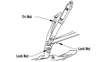
Spindle (XF HC/M)
0749-480
REMOVING 1.Position the front of the snowmobile on a safety stand; then remove the ski. 2.Remove the two cap screws and nuts securing the shock to the chassis and to the lower A-arm.
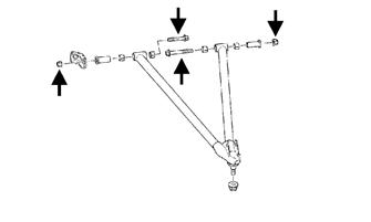
3.Remove the lock nut securing the tie rod to the spindle arm. Account for the washer on the top side. 4.Remove the machine screw and tri-nut securing the upper A-arm ball joint to the spindle. 5.Remove the lock nut securing the spindle to the lower A-arm; then using a rubber mallet, remove the lower arm from the spindle.
INSPECTING 1.Inspect the spindle for excessive wear, cracks, bends, or imperfections. 2.Inspect the A-arm bushings and axle area for wear. 3.Inspect the ski spindle axle and bearings for wear, damage, or loose fit. Replace the bearings as a set. NOTE: Replacing the ski bushings is difficult. The
existing bushings will be damaged during removal. Be careful, however, not to damage the spindle when removing the bushings. Press the new bushings into the spindle.
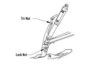
INSTALLING 1.Install the lower A-arm into the spindle and loosely secure using a new lock nut. 2.Loosely secure the upper A-arm ball joint to the spindle using the existing machine screw and the tri-nut. Raise the spindle so the upper A-arm is level; then tighten the screw securing the ball joint to the spindle to 23 ft-lb. 3.Install the shock and secure using the existing cap screws and lock nuts. Tighten to 24 ft-lb. 4.Remove the snowmobile from the support stand.
Tighten to 45 ft-lb.
NOTE: The weight of the snowmobile will allow the
ball joint to seat into the spindle before tightening the nut.
5.Place the tie rod with washer into position on the spindle arm. Secure with a new lock nut. Tighten to 32 ft-lb.
6.Install the ski.
7.Turn the handlebar fully to the right and then to the left to verify the steering moves freely.
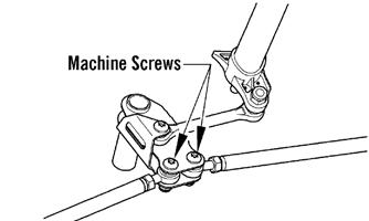
Steering Tie Rod
NOTE: To access the steering arm, the steering tie
rods must be removed.
REMOVING 1.Remove both machine screws and nyloc nuts securing the steering tie rod ends to the steering arm. Discard both nuts.
SNO-349
2.Remove the nyloc nuts securing the steering tie rod ends to the spindle arms. Account for the washers and discard both nuts.
SNO-353
3.Slide the steering tie rod out of the steering boot and out of the snowmobile.
4.Remove the screw and lock nut securing the steering tie rod end to the steering arm. Discard the nut.
SNO-350
5.Remove the lock nut securing the steering tie rod to the steering post. Discard the nut.
SNO-351
NOTE: At this point if the technician’s objective is
to remove the steering arm, the reinforcement bracket will need to be removed by drilling out the appropriate rivets.
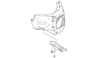
6.Remove all Torx-head screws securing the front skid plate to the chassis; then remove the cap screw and nut securing the steering arm to the chassis. Account for two washers and two bushings.
SNO-829A
INSPECTING 1.Inspect the ball joints for damaged threads or wear. 2.Inspect the tie rod for damage, unusual bends, or wear.
INSTALLING 1.Secure steering arm into position and secure using the existing cap screw, flat washers, and nut. Tighten to 96 in.-lb.
SNO-829A
2.Place the steering tie rod into position on the steering post. Secure with a new nyloc nut. Tighten to 35 ft-lb.
SNO-351
NOTE: Make sure the tie rod tab is fully seated into
the steering post and threads of the ball joint are above the nut when tightened correctly.
3.Place the tie rod end into position on the steering tie rod bracket. Secure with a new nyloc nut. Tighten to 20 ft-lb.
SNO-350
4.Slide the steering tie rod through the steering boot and into the snowmobile; then place the steering tie rod into the spindle arm with the washer. Secure with a new nyloc nut. Tighten to 32 ft-lb.

SNO-353
5.Secure the steering tie rod to the steering tie rod bracket with the screw and new nyloc nut. Tighten to 20 ft-lb.
SNO-349
Ski Alignment
CHECKING NOTE: Track tension and alignment must be prop-
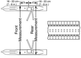
erly adjusted prior to checking or adjusting ski alignment. Ski alignment must be performed on a flat, level surface. Ski toe-out must fall within the range of 1/16-1/4 in.
1.Raise the front end of snowmobile just high enough to keep the skis from contacting the floor. 2.Turn the handlebar to the straight-ahead position.
Visually inspect the handlebar for being centered and in the straight-ahead position. 3.With the handlebar in the straight-ahead position, secure the handlebar to prevent the alignment from becoming disturbed during the remainder of the alignment procedure. NOTE: Track tension and alignment must be prop-
erly adjusted prior to placing the straightedge against the outside edge of the track.
4.Place a long straightedge against the outside edge of the track so it lies near the inside edge of the left-side ski.
729-887B
NOTE: The straightedge should be long enough to
extend from the back of the track to the front of the ski.
5.Measure the distance from the straightedge to the left-side ski wear bar bolts in two places: approximately 7-8 in. in front of the spindle and 7-8 in. behind the spindle. Record the measurements taken for the left side.
729-887A
0734-408
6.Place the straightedge against the outside edge of the track so it lies near the inside edge of the right-side ski. 7.Measure the distance from the straightedge to the right-side ski wear bar bolts in two places: 7-8 in. in front of the spindle and 7-8 in. behind the spindle.
Record the measurements taken for the right side.
8.If ski alignment is not as specified, adjust the alignment of the ski(s) not parallel to the straightedge.
! WARNING
The measurement from the front and rear wear bar bolts to the straightedge can be equal (ski parallel to the track), but the front measurement must never be less (ski toed-in) or poor handling will be experienced. The front wear bar bolt measurement to the straightedge must not exceed the measurement from the rear wear bar bolt to the straightedge (ski toed-out) by more than 5/32 in.
ADJUSTING NOTE: The following procedure can be used to
adjust the alignment of either ski.
NOTE: The rivets securing the steering boots will
have to be removed in order to adjust the inner tie rod ends.
1.Secure the steering tie rod in the centered position. 2.Loosen both spindle tie rod jam nuts on the same side as the ski to be aligned. 3.Using a wrench on the spindle tie rod “flats,” rotate the spindle tie rod until recommended specification is attained.
4.Apply blue Loctite #243 to each jam nut thread area; then tighten the jam nuts against the spindle tie rod. NOTE: Repeat this procedure on each side (if neces-
sary) until ski toe-out is within specification.
! WARNING
Neglecting to lock the tie rod by tightening the jam nuts may cause loss of snowmobile control and possible personal injury.
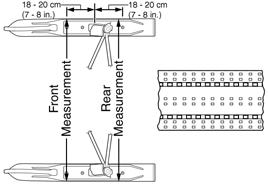
VERIFYING 1.With the handlebar in the straight-ahead position, verify ski alignment by measuring across from the outside edge of the left-side wear bar bolts to the outside edge of the right-side wear bar bolts (without using the straightedge) in two places: approximately 7-8 in. in front of the spindle and 7-8 in. behind the spindle. 2.The measurement from in front of the spindle to the outer edge of the wear bar bolts (without using the straightedge) must not exceed the rear measurement by more than 1/16-1/4 in. toe-out.
0734-408
! WARNING
The measurement taken in front of the spindle must never be less than the measurement taken behind the spindle or poor handling will be experienced. Neglecting to lock the tie rod by tightening the jam nuts may cause loss of snowmobile control and possible personal injury.
A-Arms (ZR/XF/Pantera/Norseman)
REMOVING 1.Elevate the front of the snowmobile and secure using a suitable support stand. 2.Remove the push rivets securing the steering boot to the chassis; then slide the boot away from the snowmobile.
SNO-354
6.Remove the cap screw and lock nut securing the sway bar link to the lower arm. Discard the nut.
SNO-764
7.Remove the two cap screws and nyloc nuts securing the lower arm to the chassis; then slide the boot from the arm and remove the arm.
SNO-763
3.Remove the Torx-head screws securing the front skid plate to the chassis; then remove the front skid plate. 4.Remove the ski shock absorber.
5.Remove the two lock nuts securing the spindle to the
A-arms; then using a rubber mallet, remove the arms from the spindle. Discard the nuts.
SNO-226A
8.Remove the two cap screws and lock nuts securing the upper arm to the chassis. Discard the nuts.
SNO-571
INSPECTING 1.Inspect the arm welded areas for cracks or any signs of deterioration.
2.Inspect the bearings and axles for wear or damage. 3.Inspect the arm tubing for signs of twisting or bending. 4.Inspect mounting location of the chassis for cracks or wear.
INSTALLING 1.Place the upper arm into position on the chassis and secure with the cap screws, axles, and new nyloc nuts. Tighten to 23 ft-lb.
SNO-764
4. Secure the A-arms to the spindle using two new nyloc nuts. Tighten to 45 ft-lb.
5. Install the ski shock absorber.
6. Place the front skid plate into position; then secure with the Torx-head screws.
A-Arms (XF HC/M)
NOTE: Always use new lock nuts when replacing
any steering components.
REMOVING 1.Elevate the front of the snowmobile and secure using a suitable support stand. 2.Remove the push rivets securing the steering boot to the chassis; then slide the boot away from the snowmobile.
SNO-571
2.Slide the lower arm into the boot; then place the arm into position on the chassis. Secure with the cap screws and new nyloc nuts and tighten to 65 ft-lb (front) and 45 ft-lb (rear).
PC095A SNO-763
3.Remove the Torx-head screws securing the front skid plate to the chassis; then remove the front skid plate. 4.Remove the ski shock absorber.
5.Remove the lock nut, machine screw, and tri-nut securing the spindle to the A-arms; then using a rubber mallet, remove the lower A-arm from the spindle.
0749-480A
6.Remove the two cap screws and nyloc nuts securing the lower arm to the chassis; then slide the boot from the arm and remove the arm.
SNO-226A
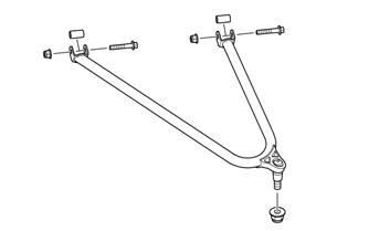
7.Remove the two cap screws and lock nuts securing the upper arm to the chassis.
SNO-572
INSPECTING 1.Inspect the arm welded areas for cracks or any signs of deterioration.
2.Inspect the bearings and axles for wear or damage. 3.Inspect the arm tubing for signs of twisting or bending. 4.Inspect mounting location of the chassis for cracks or wear. INSTALLING 1.Place the upper arm into position on the chassis and secure with the cap screws, axles, and new lock nuts.
Tighten to 23 ft-lb.
SNO-572
2.Slide the lower arm into the steering boot; then place the arm into position on the chassis with the existing bushings. Secure with the cap screws and new lock nuts and tighten to 65 ft-lb (front) and 45 ft-lb (rear).
PC095A
3. Secure the A-arms to the spindle using one new lock nut and one new tri nut. Tighten to the lock nut 45 ft-lb and the tri-nut to 23 ft-lb.
NOTE: If the upper A-arm ball joint is being
replaced, make sure the ball joint is threaded in as far as it can. Do not adjust outward or damage to the A-arm or ball joint can occur.
4.Using a 19 mm wrench, tighten the hex nut against the upper A-arm securely making sure to keep the ball joint level with the spindle. 5. Install the ski shock absorber and secure using the existing cap screws and new lock nuts. Tighten to 24 ft-lb.
6. Install the steering boot and secure using the existing push-rivets; then place the front skid plate into position. Secure with the Torx-head screws.
Ski Shock Absorber
REMOVING 1.Position the front of the snowmobile on a safety stand taking all pressure off the skis.
NOTE: On models with FOX iQS shocks, cut the
cable tie securing the harness to the shock; then disconnect the harness from the shock.
XM588
2.Remove the cap screws securing the shock absorber to the chassis and the lower A-arm; then remove the shock absorber. Account for all mounting hardware.
CLEANING AND INSPECTING 1.Inspect the shock absorber seal area for signs of excessive oil leakage. 2.Inspect the shock absorber mounting eyelet, bushings, and sleeve for wear or damage. 3.Inspect the threaded shock sleeve for damage or wear.
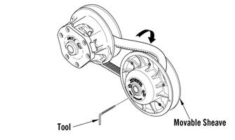
INSTALLING 1.Using the shock spring tool, place the spring on the shock absorber and secure with the retainer.
2.Adjust the retainer nut (spring adjuster) (if applicable) until the specified amount of threads are exposed between the spring adjuster and the shock housing (noted in removing) as an initial setting. 3.Install the bushings, sleeves, and spacers into each shock end; then place the shock absorber into position and secure with the cap screws and new lock nuts. Tighten the lock nuts to 32 ft-lb for ZR/XF models and 24 ft-lb for XF HC and M models.
NOTE: On models with FOX iQS shocks, route the
wire around the shock and connect to the shock making sure it clicks into place. Cable tie the wires to the shock body.
Sway Bar (ZR/XF/Pantera/Norseman)
REMOVING 1.Remove the nyloc nuts and cap screws securing the sway bar link to the lower A-arm and the sway bar.
SNO-764
2.Remove the Torx-head screws securing the sway bar mounting brackets; then pull the sway bar out of the snowmobile.
INSPECTING 1.Inspect the sway bar for any signs of twisting, fatigue, or wear. 2.Inspect the sway bar arms for cracks or damage. 3.Inspect the links, bushings, bushing retainers, and hardware for damage or wear.
INSTALLING 1.Place the sway bar into the sway bar mounting brackets; then install the sway bar into the snowmobile. Secure with the Torx-head screws and tighten to 96 in.-lb.
2.Secure the sway bar links to the sway bar and lower
A-arm with the cap screws and new nyloc nuts.
Tighten to 23 ft-lb.
Front Bumper
REMOVING/INSTALLING 1.Remove all Torx-head screws securing the front bumper; then remove the bumper. 2.With the bumper in position, install all Torx-head screws. Tighten securely.
XM588
Seat Assembly (ZR/XF/Norseman)
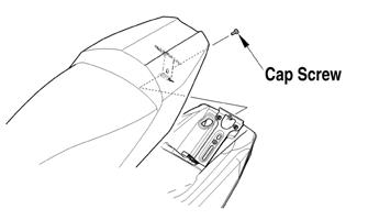
REMOVING/INSTALLING SEAT 1.Remove the cap screw securing the rear of the seat; then remove the seat.
SNO-261A
2.Route the front tab on the seat through the seat-base hold-down bracket; then install the seat and secure using the cap screw. NOTE: Note the cushion fit. If any wrinkles are
noted, remove by pulling the cushion material in the appropriate direction before securing with staples.
4.Fold the front cushion material back and onto the plastic seat base. Check for wrinkles and secure with staples and two screws. 5. Install the seat assembly.
Seat Assembly (Pantera)
REMOVING/INSTALLING 1.Lift up both seat latches and hold them in that position; then lift and remove the passenger seat. Make sure to disconnect the accessory harness.
SNO-227A
REMOVING CUSHION 1. Remove the seat assembly. 2. Using a sharp tool, pry out all staples securing the seat cover to the plastic seat base. 3. From beneath the seat foam, remove the seat wire from the two elastic loops; then remove the cover from the seat base and seat foam.
INSTALLING CUSHION 1.Position the cover over the seat foam and seat base; then pull the two elastic loops through the slots in the seat foam and secure with the seat wire. Check to make sure it is positioned straight. 2. Fold the rear edge of the cushion down and around the plastic base. Using a staple gun and 1/4 in. staples, staple the rear flap of the cushion to the plastic base in the same areas as the original staples were located. Position staples 1 in. apart. 3. Fold the sides of the cushion down around the bottom edge of the plastic seat base. Position the staples in the same area as the original staples were located.
0748-449
2.Release the lever securing the operator seat; then lift up and remove the front seat. Make sure to disconnect the seat heater harness. Remove the operator seat.
0748-419
3.To install the operator seat, route the front tab on the operator seat through the seat-base hold-down bracket; then secure the rear of the operator seat using the lever. 4.To install the passenger seat, position the front of the seat base tabs under the loops in the seat frame; then press down and secure using the two seat latches.
SNO-454A
NOTE: Be sure to connect the accessory harness.
Seat Assembly (M)
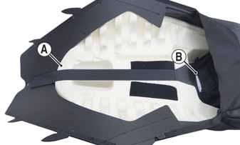
REMOVING/INSTALLING 1.Remove both Torx-head screws from the side of the seat; then remove the four tabs from the seat base from the lower console. Pull back and remove the seat cover and foam. 3.Remove the backing from the installation bag (p/n 1655-841); then adhere it to the gas tank making sure the bag covers the Velcro on the gas tank.
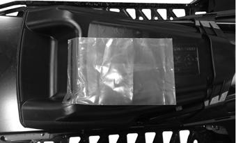
SNO-1206
4.Slide the rear of the seat cover with foam over the rear of the gas tank; then slide the four tabs into the four holes in the lower console and secure to the tunnel using two self-tapping screws. Do not over tighten. NOTE: To ease the installation of the seat cover,
carefully pry up the rear of the gas tank so the seat cover can easily slide around the rear of the gas tank.
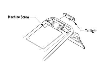
Taillight/Brake Light Assembly (ZR/XF/M)
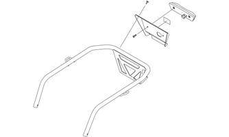
1.Remove the two machine screws securing the taillight to the taillight support; then disconnect the taillight harness connector.
0747-530
2.Position the seat foam into the seat cover by first aligning the front of the foam with the front of the seat base/cover (A); then wrap the rear of the seat base/cover over the rear of the seat foam (B). Cover the sides of the seat foam with the seat base/cover and secure using the Velcro strap.
SNO-511
2.Connect the taillight harness connector; then secure the taillight to the taillight support with the two machine screws. Tighten to 48 in.-lb.
SNO-1203A
Taillight/Brake Light Assembly (Norseman)
1.Remove the two machine screws securing the taillight cover to the rear rack. Remove the two machine screws securing the taillight to the cover; then disconnect the taillight harness connector.
ONS-102
2.Connect the taillight harness connector; then secure the taillight to the taillight cover with the two machine screws. Tighten to 48 in.-lb. 3.Secure the taillight cover to the rear rack with the two machine screws. Tighten securely.
Taillight/Brake Light Assembly (Pantera)
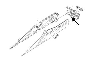
1.Remove the storage box lid; then remove the machine screws securing the taillight to the rear rack fascia. Disconnect the taillight harness connector.
XM098
2.Connect the taillight harness connector; then secure the taillight to the rear rack fascia with the screws.
Tighten to 48 in.-lb. Install the storage box lid.
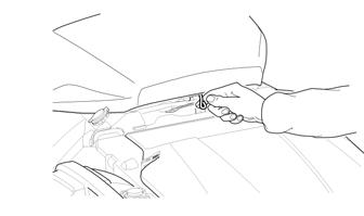
Rear Bumper/Snowflap
REMOVING BUMPER 1.Remove and retain only the two machine screws securing the rear of the skid frame assembly. 2.Place cardboard or a suitable substitute on the floor to protect the snowmobile from being scratched; then install Steering Post Stand for the standard steering models or Handlebar Stand for the adjustable steering models into the lower holes in the handlebar riser (from the left-side) and tip the snowmobile onto its left side.
CAUTION
The stand must be used when tipping the snowmobile onto the right side. Failure to use the stand may damage the oil fill neck.
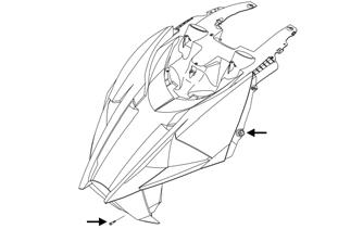
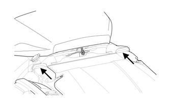
3.Swing the skid frame assembly away from the chassis; then using a 3/16-in. drill bit, remove all rivets securing the left-side of the bumper; then repeat for opposite side. 4.Remove and retain the two machine screws and nuts securing the front of the existing bumper to the chassis. 5.Remove the two rivets securing the snowflap to the bumper. Remove the bumper.
INSTALLING BUMPER 1.Align the holes in the bumper with the existing holes in the tunnel; then using new rivets, secure rear bumper to the tunnel; then secure the snowflap to the rear bumper using new rivets. 2.Secure the front of the bumper to the chassis using the existing machine screws and nuts. Tighten securely. 3.Install skid frame assembly using two existing machine screws. Tighten securely.
REMOVING SNOWFLAP 1.Drill out the four rivets securing the snowflap to the tunnel; then remove the Torx-head screw and nut. 2.Remove the snowflap.
INSTALLING SNOWFLAP 1.Secure the snowflap to the tunnel with the Torx-head screw and nut.
2.Add the appropriate rivets to secure the snowflap to the tunnel.
Windshield/Console/ Headlight
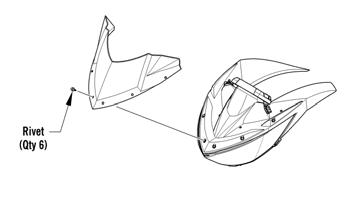
REMOVING 1.Remove both access panels and the hood.
2.Remove the screws or rivets securing the windshield to the console. Remove the windshield.
SNO-776
0750-529
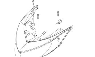
3.Remove the six screws securing the console.
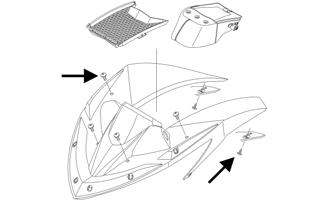
SNO-963A
4.Disconnect the gauge, electrical accessory wires, and the ignition switch. 5.Remove the three screws securing the headlight to the hood; then disconnect the headlight connector.
Remove the headlight.
INSTALLING 1.Position the headlight onto the hood; then secure the headlight using the existing screws. Connect the headlight connector. 2.Engage the side console tabs on the headlight assembly; then place the front of the console over the headlight assembly and press down until it snaps in place. 3.Secure the console to the headlight and the hood using the existing screws. Tighten securely. 4.Connect the gauge; then connect the electrical accessory wires and the ignition switch. 5.With the windshield in position, secure the windshield to the frame using the screws or rivets.
Tighten securely. 6.Install the hood and both access panels.
Headlight Bulb — Non-LED
NOTE: The bulb portion of the headlight is fragile.
HANDLE WITH CARE. When replacing the headlight bulb, the bulb assembly must first be removed from the housing. Do not touch the glass portion of the bulb. If the glass is touched, it must be cleaned with a dry cloth before installing.
1.Disconnect the headlight harness connector from the bulb; then remove the rubber grommet from the headlight housing. 2.Rotate the bulb retainer counterclockwise until it unlocks from the housing; then remove the bulb.
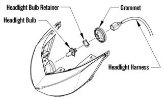
0746-096
3.Install the bulb and retainer; then rotate the retainer clockwise until it properly locks in place. 4.Install the rubber grommet; then connect the headlight harness connector to the bulb. 5.Check headlight aim (see Adjusting Headlight Aim in this sub-section). ! WARNING
Do not operate the snowmobile unless headlight beam is adjusted properly. An incorrectly adjusted beam will not provide the operator the optimum amount of light.
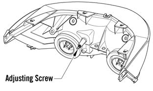
Adjusting Headlight Aim
The headlight can be adjusted for vertical aim of the HIGH/LOW beam. The geometric center of HIGH beam zone is to be used for vertical aiming. 1.Position the snowmobile on a level floor so the headlight is approximately 25 ft from an aiming surface (wall or similar surface). NOTE: There should be an “average” operating
load on the snowmobile when adjusting headlight aim.
2.Measure the distance from the floor to midpoint of the headlight. 3.Using the measurement obtained in step 2, make a horizontal mark on the aiming surface. 4.Make a vertical mark intersecting the horizontal mark on the aiming surface directly in front of the headlight. 5.Engage the brake lever lock and start the engine.
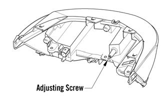
Select the headlight dimmer switch HIGH beam position. DO NOT USE LOW BEAM. 6.Observe the headlight beam aim. Proper aim is when the most intense beam is centered on the vertical mark 5 cm (2 in.) below the horizontal mark on the aiming surface. 7.Adjust the headlight using the adjusting screw on the backside of the headlight housing until correct aim is obtained. Shut the engine off; then disengage the brake lever lock.
LED
0750-309
Halogen