20 minute read
Electrical Systems

All tests of the electrical components should be made using the digital Fluke Model 77 Multimeter. Replace any component that does not have a test value within specifications. NOTE: Whenever using a digital-style tester, “open
(infinite resistance)” denotes an overload and the meter reading will be OL since the meter is not calibrated to register resistance values of that magnitude.
NOTE: Always check the appropriate fuse before
testing a component for failure.
NOTE: Whenever a part is worn excessively,
cracked, or damaged in any way, replacement is necessary.
SPECIAL TOOLS A number of special tools must be available to the technician when servicing the electrical systems.
CATT II
Description
Arctic Cat Diagnostic System Manual Laptop Diagnostic Tool Actuator Test Harness
p/n
0544-023 2256-974 0744-048 0644-518
Fluke Model 77 Multimeter
0644-559 MaxiClips 0744-041 Throttle Position Sensor (TPS) Adjustment Tool Kit 3639-891
NOTE: Special tools are available from the Arctic
Cat Service Parts Department.
Ignition System
NOTE: There must be 0.75-1.5 mm (0.030-0.060 in.)
free-play between the throttle lever and the control housing.
0752-478
TROUBLESHOOTING 1.Remove the spark plugs and visually check their condition. Replace any fouled plug. Attach the spark plugs to the high tension leads and ground them to the engine.
CAUTION
Before checking for spark, place all the engine switches in the deactivated position. In the event the engine could be flooded, engage the starter several times to clear the engine of excess fuel.
CAUTION
Never crank the engine over without grounding the spark plugs. Damage to coils and/or CDI/ECM may result.
NOTE: Make sure the ignition switch and the emer-
gency stop switch are in the ON position.
2.Crank the engine over and check for spark. If no spark is present, check to make sure the throttle cable is properly tensioned. Compress the throttle control and while holding the throttle control in this position, crank the engine over and check for spark. If spark is now present, adjust the throttle cable tension.
TESTING Throttle Control Switch 1.Disconnect the handlebar harness connector; then connect the red meter lead to the yellow wire; then connect the black meter lead to the black wire.
2.With the throttle lever in the idle position, the meter must read less than 1 ohm. If the meter reads OL (infinite resistance), replace the control assembly. 3.Move the throttle lever to the wide open position.
The meter must read OL (infinite resistance). If the meter reads less than 1000 ohms, replace the control assembly.
Throttle Position Sensor
NOTE: Two-stroke engines equipped with a throttle
position sensor have a protective feature called “fail-safe” ignition timing preventing engine damage should the TPS fail. If the TPS does fail, the engine may run normally at low RPM but will run poorly at high RPM allowing the operator to get the snowmobile to safety with no engine damage. The engine will continue to operate this way until the TPS is adjusted or replaced.
CHECKING TPS NOTE: If the snowmobile is in warranty, breaking
the seal on the idle screw jam nut or the Phillips-head screws on the TPS will void warranty. If the TPS is tested out of specification, the throttle body must be replaced. If the snowmobile is out of warranty, proceed to ADJUSTING TPS.
NOTE: The TPS should only be checked using the
CATT II Tool.
ADJUSTING TPS NOTE: Adjusting the TPS is for out of warranty
snowmobiles only.
NOTE: The TPS should only be adjusted using the
CATT II Tool.
Idle
1.12v ± 0.075v
Full-Open
4.416v ± 0.15v
REPLACING TPS NOTE: Replacing the TPS is for out of warranty
snowmobiles only.
Removing 1.Rotate the idle screw counterclockwise until it no longer contacts the throttle shaft stop. The throttle shaft should now be completely closed. 2.Disconnect TPS wiring harness from the TPS; then noting the position of the TPS, remove the two screws securing the TPS to the throttle body and remove the sensor.
Installing 1.Install the new TPS onto the throttle shaft by aligning the “flats” on the throttle shaft cam with the
“flats” on the sensor; then rotate the sensor until properly positioned on the throttle body. NOTE: Before installing the TPS harness connector,
apply dielectric grease to the connector pins.
2.Install the sensor to the throttle body. Do not tighten at this time.
3.Adjust the TPS using the CATT II Tool.
Electrical Resistance Tests
NOTE: Replace any component that does not have a
test value within specifications. If the component tests satisfactorily but is suspected to be faulty, connect the red meter lead to a component lead and the black meter lead to ground. Check for continuity between the component and ground. If continuity is observed, replace the component.
NOTE: The following test should be made using
MaxiClips and the Fluke Model 77 Multimeter set to OHMS scale.
CAUTION
Always disconnect the battery when performing resistance tests to avoid damaging the multimeter.
Charge Coil (1) 1.Disconnect the triple-wire plug from the main harness to the magneto. 2.Connect the red meter lead to the black/red wire in the plug; then connect the black meter lead to the green/red wire in the plug. 3.Resistance must be 8.8-13.2 ohms.
Charge Coil (2) 1.Disconnect the triple-wire plug from the main harness to the magneto. 2.Connect the red meter lead to the brown/white wire in the plug; then connect the black meter lead to the green/red wire in the plug. 3.Resistance must be 8.8-13.2 ohms.
Fuel Pump Coil NOTE: With the engine running, there should
14.5-17.5 DC volts supplied to the fuel pump for operation.
1.Test between the two orange wires in the four-prong connector from the magneto. 2.Resistance must be 1.52-2.28 ohms.
Injection Coil 1.Test between the two blue/white leads in the four-prong connector harness from the magneto. 2.Resistance must be 15.2-22.8 ohms.
Lighting Coil 1.Disconnect the main harness from the magneto. 2.Connect the two meter leads to each of the yellow leads in the connector from the engine. 3.Resistance must be 0.08-0.12 ohm.
Ignition Timing Sensor 1.Disconnect timing sensors 1 and 2 (green/white and brown/green) from the main harness. 2.Connect the meter leads to the sensor leads.
3.Resistance must be 148-222 ohms.
Ignition Coil (Primary) 1.Disconnect the double wire plug from the main harness to the ignition coil. 2.Connect the red meter lead to the black/white lead; then connect the black meter lead to the white/blue lead.
3.Ignition coil primary resistance must be between 0.24-0.36 ohm.
Ignition Coil (Secondary) 1.Remove the spark-plug caps from the high tension wires.
2.Connect the red meter lead to one high tension wire; then connect the black meter lead to ground. 3.Resistance must be 5040-7560 ohms.
Spark-Plug Cap 1.Remove the spark-plug caps from the high tension wires.
2.In turn on each cap, touch a tester lead to each end of the spark-plug cap. 3.Resistance must be 4000-6000 ohms.
Ignition Switch NOTE: The console must be removed to access the
ignition switch.
1.Remove the main wiring harness connectors from the ignition switch. 2.Rotate the key to the OFF position. 3.Resistance must read less than 1 ohm between the ignition switch terminals. 4.Rotate the key to the RUN position. The meter must read OL (infinite resistance).
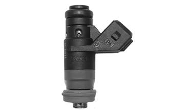
Fuel Injector 1.Disconnect the fuel injector wiring harness; then set the meter to the OHMS position.
2.Test between the two injector terminals. Resistance must be 11.4-12.6 ohms.
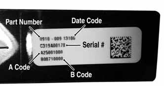
3.If not within specifications, replace the injector. NOTE: When replacing the injector, the A and B
codes must be entered using the CATT II Tool.
SNO-1235A
Coolant Temperature Sensor 1.Disconnect the coolant temperature sensor wiring harness from the main harness.
2.Test the resistance between the two leads from the sensor. Resistance must be 2.42-2.57 ohms at 68° F (20° C).
Air Temperature Sensor NOTE: The component temperature must be
known before conducting this test. Allow the engine to reach room temperature.
1.Disconnect the wiring harness from the air temperature sensor.
2.Test the resistance between the two leads from the sensor. Resistance must be 2.35-2.55 ohms at 68° F (20°C). NOTE: The air temperature sensor utilizes a therm-
istor. Resistance will change as temperature varies.
Testing Electric Oil Pump
1.Remove the right-side access panel; then remove the lower console from the skid plate. Disconnect the oil pump connector.
CWI-109A
2.Set the selector to the OHMS position. 3.Test between the two terminals. Resistance must be 1.75-1.95 ohms.
NOTE: If replacing the oil pump, the A and B codes
must be entered using the CATT II Tool. The pump must also be primed using the CATT II Tool.
Testing Voltage Regulator
NOTE: The following test should be made using a
Fluke Model 77 Multimeter.
! WARNING
Most voltages generated by the ignition system are sufficient to interrupt pacemakers! All technicians, especially those using pacemakers, must avoid contact with all electrical connections after the engine has been started.
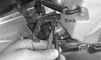
1.Remove the right-side access panel; then remove the lower console from the right-side skid plate and secure out of the way. 2.For the DC voltage test, connect the red meter lead to the red/blue wire in the accessory connector; then connect the black meter lead to the black wire in the connector.
XM412A
3.Start the engine and allow it to idle. Meter reading must be within 9-15 DC volts.
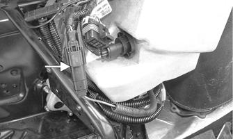
Testing Oil Level Sensor
The oil level sensor is a magnetic switch. Its operation is based on a magnet located in the float. The switch located in the stem of the sending unit is positioned through the hole in the float. When the float drops to the lower part of the stem, the magnet closes the electrical contacts (located in the stem) allowing the current to pass on to the warning light.
PC256
1.Verify the oil level is below the float; then remove the sensor from the oil reservoir by twisting and pulling out. Wipe excess oil from the sensor. 2.Unplug the sensor from the wiring harness. 3.Set the meter selector to the OHMS position. 4.Touch each of the meter leads to one of the terminals on the sensor. With the sensor in its normal position (float end down), the meter should read less than 1 ohm.
5.If the meter reads greater than 1 ohm, check to make sure good contact has been made with each of the terminals on the sensor. If the meter still reads greater than 1 ohm, replace the sensor. 6.While maintaining contact between the meter leads and the sensor, raise the float. The meter must read
OL (infinite resistance). If the meter reads less than 1 ohm, replace the sensor. 7.If the sensor tests satisfactory but the icon doesn’t illuminate with only a small amount of oil in the reservoir, verify the icon illuminates on start-up.
Testing Fuel Gauge Sender
NOTE: Before testing the sender, verify the harness
from the sender to the gauge is satisfactory.
1.Remove the hood.
2.Disconnect the fuel gauge sender unit from the main wiring harness; then connect the ohmmeter leads to the two blue sender wires.
3.Compare the reading to the following chart:
Full <20 ohms 1/2 40-56 ohms Empty 76-105 ohms
Emergency Stop Switch
RESISTANCE 1.Disconnect the stop switch connector; then set the selector to the OHMS position. 2.Connect one tester lead to one pin; then connect the other tester lead to the other pin.
ONS-118
3.With the switch in the ON position, the meter must read OL (infinite resistance). 4.With the switch in the OFF position, the meter must read less than 1 ohm resistance.
Starter Relay Solenoid
TESTING NOTE: The electric start solenoid may be tested
using either one of the following methods.
Method #1 1.Disconnect the solenoid connector from the main wiring harness.
NOTE: An in-line ammeter would measure between
2 and 4 amps of solenoid coil current flow with the battery connected.
CAUTION
NEVER connect an in-line ammeter with the large starter cables because the 200 amps of current flow will instantly damage most ammeters.
Method #2 1.Using the multimeter set to the DC Voltage position, check the relay as follows. 2.Connect the red tester lead to the positive battery terminal; then connect the black tester lead to the starter cable connection on the starter relay. The meter must show battery voltage. NOTE: Engage the brake lever lock and place the
emergency stop switch in the RUN position.
3.Engage the starter while observing the multimeter.
The multimeter should drop to 0 volts and a “click” should be heard from the relay. NOTE: If a “click” is heard and more than 1 volt is
indicated by the multimeter, replace the starter relay. If no “click” is heard and the multimeter continues to indicate battery voltage, proceed to step 4.
4.Disconnect the two-wire plug from the starter relay; then connect the red tester lead to the green wire and the black tester lead to the black wire.
5.Depress the starter button and observe the multimeter.
NOTE: If battery voltage is indicated, replace the
starter relay. If no voltage is indicated, check fuse or relay.
Fuse
TESTING 1.Remove the fuse from the fuse holder.
2.Connect the ohmmeter across the fuse end-caps. 3.The ohmmeter must read less than 1 ohm of resistance.
Ignition Switch
TESTING
CAUTION
To prevent ohmmeter damage when testing circuits on snowmobiles equipped with an electric start, be sure to disconnect the battery before testing.
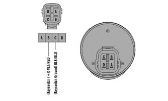
1.Disconnect the wiring harness from the ignition switch; then remove the switch from the console. Set the selector to the OHMS position. 2.Connect one tester lead to pin B; then connect the other tester lead to pin C.
ONS-131
3.With the switch in the ON position, the meter must read OL (infinite resistance). 4.With the switch in the OFF position, the meter must read less than 1 ohm resistance.
Starter Motor
NOTE: The starter motor does not need to be
removed in order to replace the pinion gear.
REMOVING 1.Remove the seat and disconnect the battery; then remove the hood and both access panels. 2.Remove all springs securing the expansion chamber and resonator; then remove the expansion chamber and resonator.
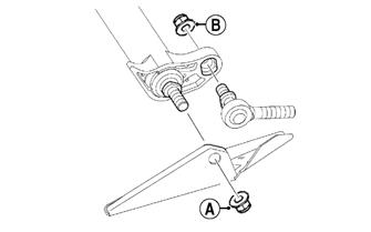
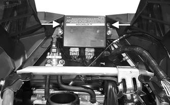
3.Remove the two screws (A) securing the heat shield to the chassis; then remove the heat shield from the two front locating pins (B) and remove the heat shield.
ZR-133

4.Disconnect the ECM; then remove the screws securing the right and left-side fascia panels to the chassis.
Remove the panels and ECM as an assembly.
EL-006A
7.Loosen the four clamps securing the throttle body; then lift up the throttle body and disconnect the coolant lines. Set the throttle body up and out of the way. 8.Remove the intake boot from the chassis.
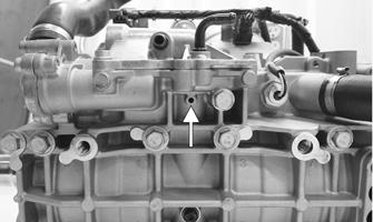
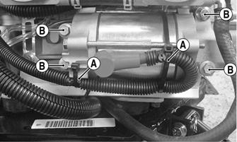
9.Remove the cable ties (A) securing the positive cable to the starter motor; then remove the nut securing the positive cable. 10.Remove the four cap screws (B) securing the starter motor to the engine.
ZR-134
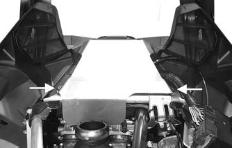
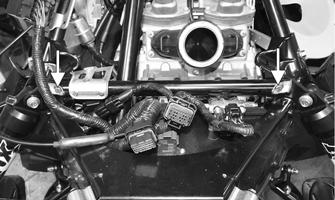
5.Remove the cap screws and lock nuts securing the shock mount bracket support to the shock mount brackets; then remove the shock mount bracket support.
EL-003A
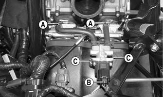
6.Remove idle speed control (ISC) hoses (A) from the top of the throttle bodies; then disconnect the ISC from the main harness (B). Remove the screws (C) securing the ISC; then remove the ISC.
CWI-108A
TESTING STARTER MOTOR NOTE: Before installing the starter motor, perform
test to ensure proper operation using the following procedure.
1.Attach a black jumper cable to a good ground on the starter.
2.Attach the opposite end of the black jumper cable to the negative post of a good 12V battery. 3.Attach the red jumper cable to the positive post of the battery. 4.Holding the starter firmly down on a work bench, touch the red jumper cable to the positive cable stud of the starter.
! WARNING
Be sure to keep clear of the pinion gear area as it will spin at a high RPM when the red cable is touched to the positive stud. Personal injury may result if contact is made with a spinning pinion.
NOTE: The starter motor must instantly spin at a
high RPM. On the 6000 the pinion must snap out against the stopper. If the motor does not spin, remove the red cable immediately. Check the battery condition and all connections.
INSTALLING 1.Secure the starter motor using the existing four cap screws (B) (threads coated with blue Loctite #243).
Tighten to 25 ft-lb.
CWI-108A
2.Secure the positive battery cable to the starter motor using the existing nut. Tighten to 72 in-lb. Secure using a cable ties (A). 3.Install and position the intake boot; then secure the throttle body to the coolant lines using the existing clamps. Tighten securely. 4.Install the throttle body into the intake flanges and the intake boot. Secure using existing clamps. 5.Install the idle speed control (ISC) hoses (A) to the top of the throttle bodies; then secure the ISC using the screws (C). Connect the ISC to the main harness (B).
EL-006A
6.Position the shock mount bracket support and secure using the existing cap screws and nuts. Tighten to 20 ft-lb.
EL-003A
7.Secure the ECM and front fascia assembly to the chassis using the existing self-tapping screws.
Tighten securely. 8.Install the resonator and expansion chamber and secure using existing springs. 9.Install the hood, left-, and right-side access panels. 10.Connect both battery cables to the battery making sure both are secure; then install the seat.
DISASSEMBLING PINION NOTE: This procedure does not require the starter
motor to be removed from the snowmobile.
1.Remove the drive clutch.
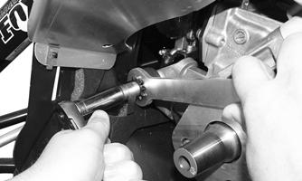
2.Install the correct side of the pinion wrench over the spring and onto the pinion gear aligning the grooves in the wrench with the teeth on the pinion gear.
XM393
XM394
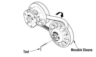
3.Install the pinion stop tool over the spring and in between the pinion stop and the pinion spring retainer.
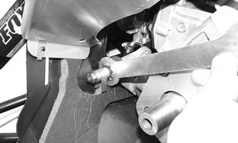
XM395
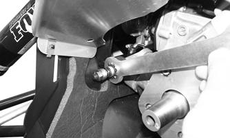
4.Using a 17 mm socket, remove the nut and washer from the pinion shaft noting that the pinion shaft has reverse thread.
XM396
5.Remove both special tools, pinion stop, spring, and spring retainer; then remove the pinion gear.
CLEANING AND INSPECTING PINION 1.Using parts-cleaning solvent, wash grease from the pinion gear. Dry with compressed air.
2.Inspect the pinion gear for wear. If the gear is worn or chipped, replace the pinion assembly. 3.Inspect the inner gear and housing. If the gear shows any signs of wear, replace the pinion assembly. 4.Inspect the inner housing for tightness and cracks. If the housing shows any signs of being loose or cracked, replace the pinion assembly. 5.Inspect the pinion return spring for wear. If the spring shows any worn areas, replace the spring.
! WARNING
When using compressed air to dry components, always wear safety glasses.
ASSEMBLING PINION 1. With Pinion Grease (p/n 1056-300) applied to the pinion gear threads, slide the pinion gear, spring retainer, pinion spring, and spring retainer onto the shaft in their original positions.
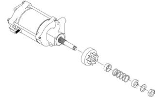
ONS-041
2.Loosely secure the components from step 1 using the existing washer and new Nut (p/n 2623-172); then install the pinion gear wrench onto the pinion gear and tighten the nut to 30 ft-lb.
XM394
NOTE: Make sure the pinion stop is able to be pushed in and rotated freely when the nut is torqued. 3.Remove the wrench and install the drive clutch.
Tighten to 51 ft-lb.
Troubleshooting Electric Start
Brake Light Switch
Problem: Hot or Smoking Wires Condition Remedy
1. System wired incor- 1.Check wiring against wiring rectly diagram
Problem: Starter Does Not Turn Over Condition Remedy
1. Battery discharged 1.Check/charge the battery 2. Connection loose 2.Check tightness of all connections 3. Grounding improper 3.Check ground connections 4. Fuse blown — not 4.Check — replace fuse installed
TESTING/REMOVING 1.Disconnect the brake light switch gray and brown two-wire connector (located near the brake lever).
2.To test the brake light switch, connect one tester lead to the brown terminal; then connect the other lead to the gray terminal.
ONS-116
3.With the brake lever compressed, the meter must read 1 ohm or less resistance. With the brake lever released, the meter must read OL (open). If the meter does not read as specified, the brake light switch is defective and must be replaced. 4.To remove the switch, pry the brake switch from the brake assembly.
ONS-117
INSTALLING 1.Press the switch into the brake assembly making sure it is fully seated. 2.Connect the switch harness to the main wiring harness. Position the wires so they will not be either pinched or come into contact with any moving components. Cable tie as needed. Start the engine and check the switch for proper operation.
Testing Headlight Dimmer Switch
1.With the key off, open the hood; then disconnect the 12-pin handlebar connector from the main harness. 2.Read continuity between the red/yellow and the blue wires for the high beam (red/yellow to white should be open circuit). 3.Read continuity between the red/yellow and the white wires for the low beam (red/yellow to blue should be open circuit). 4.The voltage check can read 12-15 VDC feeding the control, red/yellow to black, On high beam, 12-15
VDC blue (+) to black (-), and on low beam, 12-15
VDC white (+) to black (-).
Testing Handlebar Warmer Elements
NOTE: Resistance will vary due to temperature;
therefore, this test should be made at room temperature of 20° C (68° F).
NOTE: To access the element connectors, the han-
dlebar control assembly for the side being tested must be removed.
1.Disconnect the handlebar warmer three-wire connector.
2.In the element connector, connect one ohmmeter lead to the green/white lead; then connect the other ohmmeter lead to the green lead. 3.The meter must read between 12.6-15.4 ohms.
4.In the element connector, connect the ohmmeter between the green/blue and green lead wires. 5.The meter must read between 6.3-7.7 ohms.
6.Replace any element measuring less than or more than the specified amount. NOTE: Repeat test for the other element. 7.Connect the leads; then install the handlebar control assembly.
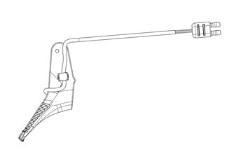
Testing Thumb Warmer Element
NOTE: Resistance will vary due to temperature;
therefore, this test should be made at room temperature of 20° C (68° F).
1.Disconnect the thumb warmer two-wire connector.
ONS-120
2.Connect one ohmmeter lead to the one lead; then connect the other ohmmeter lead to the other lead.
Testing Handlebar Warmer/Thumb Warmer Switch
NOTE: The switch should only be checked using the
CATT II Tool. Instructions will be included with the tool.
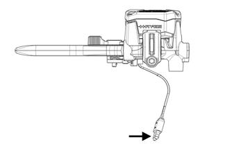
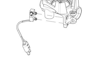
Testing Tether
1.Disconnect the two-wire connector from the tether switch. 2.Connect one ohmmeter lead to one pin; then connect the other ohmmeter lead to the other pin. 3.With the tether cord installed on the switch, the meter must read less than 1 ohm of resistance. With the tether cord removed from the switch, the meter must read OL (infinite resistance).
Testing Speedometer Sensor
NOTE: The following test should be made using
MaxiClips and the Fluke Model 77 Multimeter set to the DC Volt scale.
NOTE: Prior to testing the sensor, inspect the
three-wire connector on the sensor harness for contamination, broken pins, and/or corrosion. With the engine running, note that a power supply of 10.8-14.4 DC volts exists at the main harness/speedometer connector.
XM208A
1.Elevate the rear of the snowmobile onto a suitable safety stand. 2.Set the meter selector to the DC Voltage position. 3.At the sensor side of the plug-in, connect the red
MaxiClip and meter lead to the white/orange lead; then connect the black MaxiClip and meter lead to the black lead.
4.Connect a positive 12-volt DC power supply to the red/blue wire; then connect a negative cable to the black wire from the main harness side of the plug-in. 5.Rotate the driven clutch. The meter must read 0 volts and 12 volts alternately.
Testing Shift Switch
NOTE: The switch should only be checked using the