19 minute read
Fuel Systems

This section has been organized for servicing the fuel systems; however, some components may vary from model to model. The technician should use discretion and sound judgment when removing/disassembling and assembling/installing components. Whenever any maintenance or inspection is made on the fuel system where fuel leakage may occur, there should be no welding, smoking, or open flames in the area. NOTE: Whenever a part is worn excessively,
cracked, or damaged in any way, replacement is necessary.
SPECIAL TOOLS A number of special tools must be available to the technician when servicing the fuel systems.
CATT II
Description p/n
0554-023
EFI Analyzer
0744-049 EFI Diagnostic System Manual 2257-850 EFI Diagnostic System Manual (Instructions) 2259-020 Fluke Model 77 Multimeter 0644-559 Fuel Hose Clamp Tool 0644-545 EFI Fuel Pressure Test Kit 0644-587 Vacuum Test Pump 0644-131 Fuel Pump Installation Tool Kit 0744-074 Laptop Diagnostic Test Kit 0744-050 Laptop Diagnostic Tool 0744-060 Oil Injection Usage Tool 0644-007
NOTE: Special tools are available from the Arctic
Cat Service Parts Department.
EFI System
INTRODUCTION The Arctic Cat EFI System operates off a series of coils located on the stator and is made up of the following components: 1.An engine control module (ECM) calculates input from sensors (exhaust temperature sensor, air temperature sensor, coolant temperature sensor, throttle position sensor, ignition timing sensor, barometric pressure sensor, and a knock sensor) to provide the engine with the correct fuel mixture and timing for optimum operation. 2.Charge coils (1 and 2), located on the stator, provide
AC voltage to the ECM/regulator/rectifier where AC voltage is converted to DC voltage. 3.A fuel pump coil located on the stator operates the low voltage, high output fuel pump. At cranking speed, the high output fuel pump provides enough fuel to charge the fuel rail. 4.An injector coil located on the stator provides the injectors with DC voltage for operation through the
ECM.
5.A lighting coil located on the stator plate provides output to the regulator/rectifier (8000) to operate accessories and the lighting system.
FLOODED ENGINE If the engine should become flooded, set the brake lever lock, compress the throttle lever to the full-open position, and crank the engine over until it starts and clears itself. Release the brake lever lock.
FUEL SYSTEM The fuel is first drawn into the electric fuel pump through multiple pick-up valves and hoses. The fuel is then routed through a high-pressure fuel hose to the fuel rail. The fuel pressure is maintained in the fuel rail by the fuel regulator. With the fuel pressure maintained at a constant psi, the ECM evaluates the information it receives from the electrical sensors and opens the injectors for precise periods of time (pulse widths) to meet engine demands. NOTE: The entire EFI system depends on all coils
functioning properly on the stator.
Individual Components
ECM The ECM is the brain of the EFI system. It uses sensor inputs to determine the correct fuel/air ratio for the engine given the existing conditions of altitude and temperature.
If any of the sensors should fail while the engine is running, the ECM will sense a problem and go into a “fail safe” mode. This is an over-rich condition and will greatly reduce performance. However, the engine will be protected from a possible lean condition and engine damage. The ECM is equipped with a self-diagnostic system utilizing the service icon in the speedometer/tachometer and remains illuminated when a problem exists with any of the sensors. The technician can determine the problem sensor by reading the code shown on the readout screen and applying it to the ECM Diagnostic Codes chart (see Self-Diagnostic System/Codes in this section). NOTE: The ECM cannot be repaired. If the ECM is not receiving current from one of the output coils on the stator, that circuit will not operate. Coils on the stator are the charge coils operating the ECM, the injector coil which operates the injectors, the fuel pump coil which operates the fuel pump, and the lighting coil/chassis control unit operating all accessories and the lighting system.
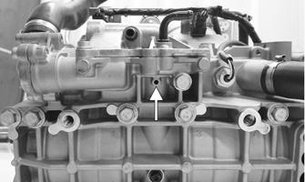
Removing 1.Remove the expansion chamber. 2.Remove the two Torx-head screws securing the rear portion of the ECM heat shield; then remove the shield.
3.Disconnect the wire harness leads from the ECM; then remove the two cap screws securing the ECM.
Remove the ECM.
Installing 1.Secure the ECM to the chassis using the existing cap screws; then connect the wiring harness to the ECM. 2.Secure the front of the ECM heat shield into the tabs; then secure the back of the ECM heat shield using the existing Torx-head screws. Install the expansion chamber.
NOTE: Make sure all connectors are clean and
tight. Apply dielectric grease to all connectors.
COOLANT TEMPERATURE SENSOR This sensor detects coolant temperature. The ECM measures the current flow through the sensor to ground. From this measurement, the ECM can determine the engine coolant temperature and calculate the correct fuel/air mixture ratio.
NOTE: If the coolant temperature rises above 75°C
(167°F), the temperature sensor starts to richen the fuel mixture. At this time, the check engine light will flash constantly. Once the engine coolant temperature reaches the specified temperature 90° C (194° F), the temperature sensor will signal the ECM to go into the rich mode to protect the engine while overheating. At this time, the check engine light will be constantly on.
TEMPERATURE MANIFOLD ABSOLUTE PRESSURE (TMAP) SENSOR
This sensor detects both air temperature and air pressure within the air intake system that provides instantaneous information to the ECM.
1.Disconnect the sensor connector from the sensor located on top of the intake boot. 2.Select DC Voltage on the tester and power up the
ECM from the diagnostic power plug. 3.Connect the black tester lead to the black/blue wire and the red tester lead to the orange/blue wire. The meter should read 4.5-5.5 DC volts. If the meter does not read as specified, check the ECM connector or wiring. 4.Connect the sensor to the harness; then using Maxi-
Clips, connect the red tester lead to the white/blue wire and the black tester lead to the black/blue wire.
With the ECM powered from the diagnostic power plug, compare the voltage reading to the voltage chart-air pressure. The voltage reading should approximately correlate to the atmospheric pressure where the test was taken.
Altitude (Meters) Pressure (kPa) Output (Volts)
305 97.7 4.20 1829 81.2 3.48 3048 69.7 2.98 THROTTLE POSITION SENSOR This sensor is a potentiometer (essentially, a resistor). This sensor transforms the throttle-valve position into output voltage to the ECM. In addition, the sensor detects the opening or closing speed of the throttle valve and feeds that rate of voltage change to the ECM. NOTE: The input from the throttle position sensor
is one of the main inputs for the ECM calculation of fuel/air mixture ratio.
IGNITION TIMING SENSOR This sensor is triggered by teeth precisely mounted to the flywheel flange. Each time a tooth rotates past the sensor, a signal is sent to the ECM. From this signal, the ECM determines ignition and injection timing and RPM.
FUEL INJECTORS A fuel injector is an electromagnetic injection valve controlled by a signal from the ECM. The coil used in the injector is a high-pressure resistance type. The ECM determines the optimum fuel injection time and duration based on signals from the sensors. When voltage is sent to the fuel injector, it energizes the coil and opens the needle valve, thereby injecting fuel. Because the fuel pressure (between fuel line and manifold) is kept constant, the amount of fuel injected is determined by the duration of time the valve is open and manifold pressure.
CWI-106
Removing 1.With both access panels, hood, seat, and the gas tank removed, remove the nuts securing the fuel rail to the back of the cylinders. 2.Pull the fuel rail with the injectors from the cylinders and disconnect the wiring harness from each injector. 3.Carefully remove the injector from the fuel rail.
Account for both gaskets.
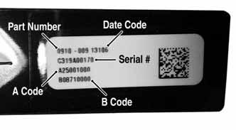
Installing NOTE: If installing new injectors, be sure to leave
the tag on the injector(s) as the codes A and B and the cylinder (MAG or PTO side) must be entered using the CATT II Tool.
SNO-1235A
1.Lightly oil the injector seals using the C-TEC2 engine oil; then carefully install the injector into the fuel rail.
2.Connect the wiring harness to the injectors; then install the fuel rail with injectors into the back of the cylinders. Secure using the existing nuts. Tighten to 102 in-lb.
FUEL PRESSURE REGULATOR The fuel pressure regulator maintains the fuel pressure at a constant specified level.
EXHAUST TEMPERATURE SENSOR This platinum, thin-film sensor detects the exhaust air temperature in the exhaust system. The ECM sends current to this sensor, and (depending on the temperature) the sensor will pass a portion of that current to ground. The ECM measures how much current passes through the sensor to ground. From this measurement, the ECM determines the exhaust air temperature and adjusts the fuel, ignition timing, and APV calibration. Resistance will increase as the temperature rises.
FUEL PUMP CIRCUIT The fuel pump and its circuit are provided with current from the fuel pump coil on the stator. For this circuit to function correctly, five components must be properly functioning. Check the following components before considering the fuel pump assembly to be defective:
A.Fuel pump coil — see coil test procedure.
B.Emergency stop switch and ignition switch must be ON.
C.Fuel pump — see fuel pump test procedure. D.Wiring harness and connectors — clean the connectors and test the harness.
E.ECM.
KNOCK SENSOR This sensor controls engine knock or detonation. The knock sensor assesses structure borne noise (vibrations) caused by rapid pressure rises (detonation) in either cylinder and performs calibration adjustments to the necessary cylinder via the ECM limiting damage to internal engine components. Detonation can be caused by many variables including poor fuel quality, lean operating conditions, or modified engine components/systems.
Self-Diagnostic System/Codes
NOTE: For testing the EFI system, refer to the
CATT II manual.
INTRODUCTION The Diagnostic Code Alarm is controlled by the ECM. If a code and the word ALARM illuminates while the engine is running, the ECM is receiving input that is outside of its established parameters.
CWI-105A
Code Trouble
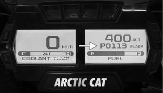
C1500 Right Ski Shock Stepper Motor Stall Detection C1505 Left Side Shock Stepper Motor Stall Detection C1510 Front Skid Shock Stepper Motor Stall Detection C1515 Rear Skid Shock Stepper Motor Stall Detection C1520 Suspension Module Supply Voltage Low C1521 Suspension Module Supply Voltage High C1522 Suspension Module Checksum Error C1523 Right Ski Shock Stepper Motor Coil A Circuit Malfunction C1524 Right Ski Shock Stepper Motor Coil B Circuit Malfunction C1525 Left Ski Shock Stepper Motor Coil A Circuit Malfunction C1526 Left Ski Shock Stepper Motor Coil B Circuit Malfunction C1527 Front Skid Shock Stepper Motor Coil A Circuit Malfunction C1528 Front Skid Shock Stepper Motor Coil B Circuit Malfunction C1529 Rear Skid Shock Stepper Motor Coil A Circuit Malfunction C1530 Rear Skid Shock Stepper Motor Coil B Circuit Malfunction C1600 Thumb Warmer Open Circuit C1601 Thumb Warmer Circuit Short to System Ground C1602 Thumb Warmer Circuit Short to System Power C1603 Hand Warmer Open Circuit C1604 Hand Warmer Circuit Short to System Ground C1605 Hand Warmer Circuit Short to System Power P0112 Intake Air Temp Sensor 1 Circuit Low P0113 Intake Air Temp Sensor 1 Circuit High P0117 Coolant Temp Sensor 1 Circuit Low P0118 Coolant Temp Sensor 1 Circuit High P0122 Throttle Position Sensor Circuit Low P0123 Throttle Position Sensor Circuit High P0261 Cylinder 1 Injector Circuit Low P0264 Cylinder 2 Injector Circuit Low P0324 Knock Control System Error P0327 Knock Control 1 Circuit Low
P0328 Knock Control 1 Circuit High P0351 Ignition Coil (A) Primary/Secondary P0352 Ignition Coil (B) Primary/Secondary P0545 Exhaust Temp Sensor Circuit Low P0546 Exhaust Temp Sensor Circuit High P1000 Oil Pump Flow Not Programmed P1001 Injector 1 Offset Not Programmed P1002 Injector 2 Offset Not Programmed P1003 Oil Pump Outlier P1004 ISC Outlier P1005 Regulator Voltage Circuit Low P1006 Regulator Voltage Circuit High P1007 Fuel Pump Circuit Low P1008 Fuel Pump Circuit High P1009 Speed Sensor Malfunction P1261 Injector Circuit/Open - Cylinder 1b P1264 Injector Circuit/Open - Cylinder 2b P1324 Knock Control System Activated P1329 Knock Sensor Loose Detection P1617 Starter Relay Circuit Short to Ground P1636 Crank Angle Sensor Circuit P1639 Exhaust Valve Position Sensor Circuit Low P1640 Exhaust Valve Position Sensor Circuit High P1645 Exhaust Valve System Malfunction P1646 Exhaust Valve Actuator Self-Cleaning Open Error P1647 Exhaust Valve Actuator Short Error P1755 Engine RPM Sensor Circuit Malfunction P2228 Barometric Pressure Sensor (A) Circuit Low P2229 Barometric Pressure Sensor (A) Circuit High P3001 Control Module Improper Shutdown U0132 Lost Communication with Suspension Control Module U0155 LCD Gauge Communication Lost U1000 Vehicle Not Registered or Invalid PIN Entered U1001 Vehicle Not Registered and Vehicle Limits Enabled U1212 Lost Communication with Left Handlebar Control
The fuel system and the ignition system remain two separate systems. In a no-start situation, first determine if the problem is caused by lack of spark or by a fuel delivery problem or by an internal engine condition (low cylinder compression for example). Once the problem area has been determined, check the components involved using the Fluke Model 77 Multimeter or the EFI Analyzer depending on the test being made.
Fuel Pressure Regulator
1.Using the Fuel Pressure Test Kit, connect the tester to the regulator fuel inlet. NOTE: A short piece of 3/8 in. I.D. hose will be
needed to make the above connections.
2.Pressurize the regulator to 28-31.3 psi. Turn the pressure tester shut off valve to the OFF position.
Observe the gauge for several minutes and note any loss of pressure. If pressure begins to drop, the cause may be a ruptured diaphragm, worn spring, or leaking valve. If the regulator fails to build or maintain pressure, replace the regulator. NOTE: If the pressure drops, check the hose con-
nections to ensure no leaks exist.
Throttle Body Assembly
REMOVING NOTE: The expansion chamber, shock mount
bracket support and air silencer must be removed for this procedure (see the Engine-Related Items section).
1.Disconnect the TPS from the wiring harness. 2.Remove both hoses securing the ISC to the throttle body; then remove the coolant hoses from the throttle body assembly and plug them to prevent leakage. 3.Loosen the clamps securing the throttle body assembly to the intake manifolds. Slide the throttle body assembly out of the manifolds; then loosen the jam nut securing the throttle cable and remove. 4. Remove the throttle body.
INSTALLING 1.Position the intake boot into the chassis.
2.Attach the throttle cable to the throttle body; then secure with jam nut. 3.Install the coolant hoses to the throttle body and secure using the clamps. 4.Place the throttle body assembly into position into the intake manifolds. Secure with the clamps. 5.Connect the wiring harness to the TPS; then position the intake boot over the throttle body and secure using the clamps. 6.Connect the ISC hoses to the throttle body using the clamps.
Throttle Cable
REMOVING 1.Loosen the throttle cable from the bracket; then remove the throttle cable from the pulley on the throttle body lever shaft. 2.Remove the cable ties securing the throttle cable. 3.Remove the throttle cable ends from the throttle lever and from the throttle control housing.
INSTALLING/ADJUSTING 1.Install the throttle cable into the throttle control assembly making sure the cable snaps into place. 2.Install the throttle cable end on the throttle lever.
3.Route the throttle cable from the throttle control assembly to the throttle body assembly and oil-injection pump; avoid any sharp bends or moving components.
4.Attach the throttle cable to the pulley on the throttle body shaft.
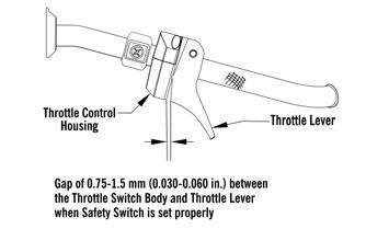
5.Secure the throttle cable to the handlebar and steering post with cable ties. 6.Adjust the throttle cable tension by turning the jam nuts in the appropriate direction until 0.030-0.060 in. free-play exists in the throttle lever and the butterfly completely opens and closes. Tighten the jam nuts securely.
0752-478

CAUTION
Compress the throttle control lever to ensure free movement. If the throttle cable sticks or binds, correct the problem before starting the engine.
7.Synchronize the oil-injection pump.
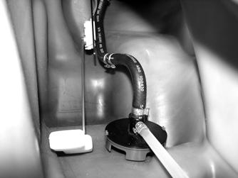
Fuel Pump
TESTING 1.Remove the right- and left-side access panels and the hood; then remove the seat and the console. 2.Disconnect the gasline hose connector hose from the outlet of the fuel pump by pressing inward on the connector, pressing in the release buttons, and finally pulling back on the hose.
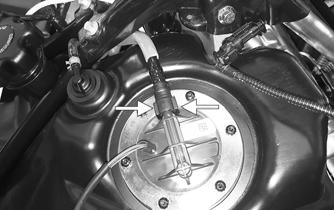
WARNING
Since the fuel supply hose may be under pressure, remove it slowly to release the pressure. Place an absorbent towel around the connection to absorb gasoline; then remove the hose slowly to release the pressure. Always wear safety glasses when removing the fuel hoses.
4.Start the engine. Fuel pressure should be 58-62 psi. NOTE: If fuel pressure is not as specified, the pump
is defective and must be replaced.
5.Disconnect the fuel pump from the main wiring harness.
6.Connect the positive lead of a 12-volt power supply to the red wire and the negative lead of the 12-volt power supply to the black wire. 7.The pump should operate (it would be heard running). NOTE: If the fuel pump fails to operate, reverse the
power supply at the fuel pump connector allowing the motor to run in the opposite direction. This will verify that nothing has entered and/or obstructed the pump.
NOTE: If the fuel pump still fails to operate, the
pump is defective and must be replaced.
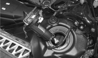
REMOVING 1.Remove the right- and left-side access panels and the hood; then remove the seat and the console. 2.Disconnect the gasline hose connector hose from the outlet of the fuel pump by pressing inward on the connector, pressing in the release buttons, and finally pulling back on the hose.
ZR-142
WARNING
Since the fuel supply hose may be under pressure, remove it slowly to release the pressure. Place an absorbent towel around the connection to absorb gasoline; then remove the hose slowly to release the pressure. Always wear safety glasses when removing the fuel hoses.
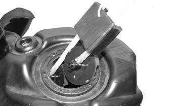
3.Remove and retain the six Torx-head screws securing the fuel pump in the fuel tank; then remove the retaining ring. 4.Carefully remove the fuel pump and fuel pickup assembly from the gas tank noting the orientation of the fuel pump outlet for assembling purposes.
SNO-702
NOTE: If the fuel pickup assembly is not being
replaced, inspect the screens for any tears or obstructions. Also check the hoses and replace if necessary.
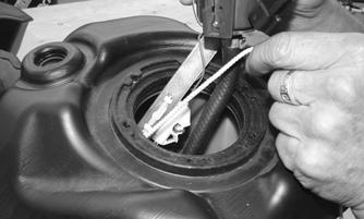
INSTALLING 1.Slide Fuel Pump Installation Tool onto the fuel hose near the “Y” fitting until the tool touches the middle pickup. The two rear pickups should be pulled together.
SNO-704
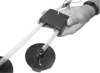
2.Carefully push the fuel pump assembly down and back into the fuel tank until the white fuel sensor (below the fuel pump) is flush with the fuel pump mounting surface.
SNO-744
NOTE: Tip the fuel pump assembly to one side
enough to allow the tool to be removed.
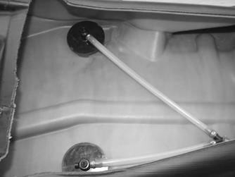
NOTE: When the fuel pump hose assembly is
installed correctly, the two rear pickups will lie flat in the rear of the fuel tank.
SNO-791
4.Make sure the front pickup will sit flat on the bottom of the tank with no kinks in the fuel hose.
SNO-705
3.While holding the fuel pump with the white fuel sensor in this position, pull the tool up to the tank opening with the retrieval cord.
SNO-706
5.Install the retaining ring over the fuel pump and secure the fuel pump to the gas tank assembly using the existing Torx-head screws. Tighten to 40 in.-lb.
CAUTION
Use care not to over tighten the retaining plate screws or damage to the gas tank may result.
6.Connect the fuel pump harness connector to the main harness and secure to the retaining ring with a cable tie; then secure the gasline hose to the fuel pump making sure it locks into place.
Troubleshooting
Problem: Too Rich Condition Remedy
1. Diagnostic trouble code activated 1.Replace problem sensor 2. Fuel pressure too high 2.Replace regulator 3. Injectors leaking 3.Replace injectors
Problem: Too Lean Condition Remedy
1. Diagnostic trouble code activated 1.Replace problem sensor 2. Fuel pressure too low 2.Replace regulator/fuel pump 3. Vent hose obstructed 3.Remove obstruction INSTALLING
Electric Oil Pump
1.Install the pump assembly into the oil tank and align with the two mounting holes; then secure the pump to the tank using the two screws (threads coated with blue Loctite #243). Tighten to 60 in.-lb.
REMOVING 1.Remove the right-side access panel; then remove the
Torx screw securing the right-side skid plate and secure it out of the way. 2.Using a handlebar stand, carefully tip the snowmobile onto the left side.

NOTE: When removing the oil pump assembly,
make sure the oil level is low enough so when the pump is removed that oil does not leak out of the oil tank.
3.Remove all four hoses from the oil pump assembly; then disconnect the oil pump harness and remove the two screws securing the oil pump to the oil tank.
CWI-112
4.Carefully remove the oil pump from the oil tank. NOTE: Do not disassemble the oil pump as it will
only be serviced as a assembly.
SNO-356
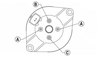
2.Install the two clear smaller hoses to the smaller front and rear terminals (A); then install the hose from the center cavity of the crankcase to the top terminal (B). Install the hose from the fuel rail to the lower terminal (C). Secure using the existing clamps.
SNO-355A
3.Secure the right-side skid plate using the existing screw.
NOTE: If a new oil pump is being installed, be sure
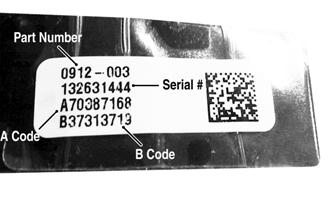
to enter the A and B codes using the CATT II Tool.
SNO-1236A
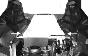
Gas Tank
REMOVING 1.Remove the hood, access panels, and seat. 2.Disconnect the reverse alarm; then remove the two machine screws securing the upper console. Remove the console.
3.Remove and retain all cap screws securing the rear spar tubes to the chassis and steering support.
Account for inserts and nuts.
XM210A
XM212A ZR-142
INSTALLING 1.Install the gas tank; then connect the gasline hose, vent hose, and fuel pump harness. 2.Install the rear spar tubes and secure to the chassis and steering support using the four cap screws.
Tighten to 23 ft-lb.
XM210A
XM212A
3.Connect the reverse alarm; then use the two machine screws to secure the upper console. 4.Install the console; then install the seat, hood and both access panels.