41 minute read
Drive Train/Track/Brake Systems

This section has been organized into sub-sections for servicing drive train, track, and brake systems; however, some components may vary from model to model. The technician should use discretion and sound judgment when removing and installing components. NOTE: Whenever a part is worn excessively,
cracked, or damaged in any way, replacement is necessary.
SPECIAL TOOLS A number of special tools must be available to the technician when servicing the drive train, track, and brake systems.
Description
Drive Clutch Bolt Tool Drive Belt Deflection Tool Bearing Removal and Installation Tool Brake Disc Socket Movable Sheave Bearing Tool Clutch Alignment Bar Drive Clutch Puller Drive Clutch Spanner Wrench Driven Clutch Compressor Tool Rear Suspension Spring Tool Brake Caliper Bearing Puller
p/n
0644-281 0644-424 0644-167 0644-481 0644-594 0744-097 0744-062 0644-136 0644-444 0144-311 0744-067
NOTE: Special tools are available from the Arctic
Cat Service Parts Department.
CAUTION
Never attempt to substitute any other drive clutch puller for the recommended puller or severe clutch damage will occur.
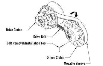
Drive Belt
If the drive belt is longer than specified, the drive clutch and driven clutch will not achieve full shift ratio. This will result in poor acceleration and a decrease in top speed. If the drive belt is shorter than specified, the starting ratio will be higher causing the belt to slip. A too-short drive belt will cause a bog on engagement and will not allow the engine to reach peak RPM. NOTE: A thinly-worn drive belt may produce the
same effect as one that is too long.
NOTE: A stiff belt causes a HP loss to the track. As
a belt warms up, it gets more flexible and transmits power with less HP loss.
NOTE: When installing a new drive belt, see After
Break-In Checkup — Drive Belt Break-In in the General Information section.
REMOVING 1.Set the brake lever lock; then remove the left-side access panel. Loosen the 1/4 turn on the lower console.
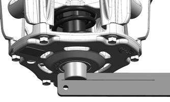
2.Using Drive Belt Deflection Tool, thread the tool clockwise into the driven clutch until the movable sheave opens far enough to remove the drive belt.
743-067B
INSTALLING 1.Place the belt (so the part number can be read) between the sheaves of the drive clutch.
2.With the sheaves fully apart, roll the belt over the stationary sheave. 3.With the drive belt properly positioned in the drive clutch and driven clutch, turn the belt tool counterclockwise, release the brake lever lock, and roll the belt back and forth to allow the driven clutch sheaves to fully close. 4.After the belt is installed properly, secure the access panel.
Drive Clutch
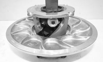
CHANGING CAM ARMS/SPRING Removing 1.Using Drive Clutch Bolt Tool, remove the Torx-head screw and lock washer securing the drive clutch to the crankshaft.
NOTE: Before installing the clutch puller, apply oil
to the threads of the puller and a small amount of grease to the tip of the puller.
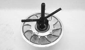
2.Using the Drive Clutch Puller and the Drive Clutch
Spanner Wrench, tighten the puller. If the drive clutch will not release, sharply strike the head of the puller. Repeat this step until the clutch releases.
3.Remove the drive clutch from the engine compartment.
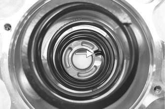
Disassembling NOTE: Note the timing marks on the cover, spider,
and movable sheave. These must be aligned when assembling the drive clutch for balance purposes.
1.Loosen the screws securing the cover. Remove every other cap screw from the cover; then while firmly holding the cover, remove the three remaining screws equally. 2.Remove the cover and spring. 1.With the cam arm pin properly positioned between the clutch tower, position the two thrust washers on each side of the cam arm with the straight edges against the bottom and outside of the clutch.
SNO-545
3.Remove the shoulder screw, washer, and lock nut securing the cam arm. Account for two thrust washers.
SNO-546
Cleaning and Inspecting 1.Using parts-cleaning solvent, wash grease, dirt, and foreign matter off all components; dry with compressed air.
2.Remove any drive belt dust accumulation from the stationary sheave, movable sheave, and bushings using parts-cleaning solvent only. 3.Inspect stationary sheave, movable sheave, spider, and cover for cracks or imperfections in the casting. 4.Inspect the shoulder screws for wear or bends. 5.Inspect the spring for distortion, cracks, or wear. 6.Inspect rollers for damage or wear.
! WARNING
Always wear safety glasses when using compressed air to dry components.
SNO-546A
2.Install washer onto the shoulder screw and install in through the clutch, thrust washers, and the cam arm.
Secure using new lock nut. Tighten to 50 in.-lb. 3.Place the spring and cover into position making sure the timing mark (X) on the cover is properly aligned with the spider and the movable sheave; then compress the spring and install the screws. In a crisscross pattern, tighten evenly to 120 in.-lb.
SNO-545
CAUTION
Care must be taken when installing the cover not to damage the bushing.
Installing NOTE: Before installing the drive clutch, be sure to
wipe both the crankshaft taper and clutch mounting taper clean using a clean towel.
1.Place the drive clutch into position on the crankshaft. 2.Using Drive Clutch Spanner Wrench to hold the drive clutch, secure using the cap screw and high collar washer. Tighten to 51 ft-lb.
Assembling NOTE: The drive clutch rotates counterclockwise
and the shoulder screw should be installed in the direction of rotation.
CAUTION
When installing the drive clutch, do not tighten the cap screw with any kind of impact tool. Tighten cap screw using a hand torque wrench only. Failure to do so could result in stationary sheave damage.
5.Start the engine and let the engine idle for 1-2 minutes; then shut the engine off and torque the cap screw again to 51 ft-lb.
! WARNING
Never operate the engine without the belt guard/access panel secured.
Driven Clutch
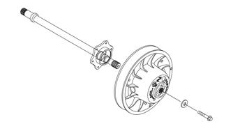
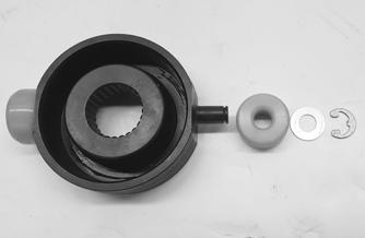
REMOVING 1.Remove the left-side access panel; then remove the cap screw and washer securing the stationary sheave to the driven shaft.
SNO-544
2.Slide the stationary sheave off the driven shaft and account for the drive belt and offset shims.
SNO-547
3.Slide the movable sheave off the driven shaft.
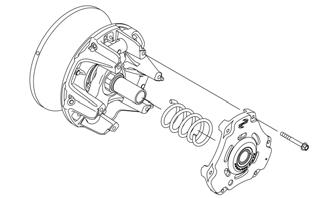
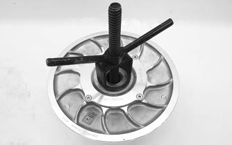
DISASSEMBLING 1. Place the movable sheave on the Driven Clutch
Compressor Tool with the torque bracket facing up; then install the compressor flange and handle against the torque bracket.
2. Apply heat to the screws securing the torque bracket to the movable sheave; then remove the screws.
CAUTION
Do not allow the compressor tool to touch either of the driven clutch bushings as it may cause damage.
XM342
3.Release the compression of the spring by removing the wing nut; then remove the torque bracket, spider assembly, and the driven clutch spring.
XM344
CLEANING AND INSPECTING 1.Using parts-cleaning solvent, wash grease, drive belt dust, and foreign matter off all components.
2.Inspect the rollers and spider for damage, cracks, or wear.
3.Inspect the sheaves for any gouges, cracks, or other damage. Also, inspect threaded areas of sheaves for damaged or stripped threads. 4.Inspect the torque bracket for cracks or damage. The ramp portions of the bracket must be free of gouges and damage. 5.Inspect spring for distortion, crystallization, or breaks.
6.Inspect the torque bracket and movable sheave bearings for wear. If wear is present, replace the bracket or sheave. CAUTION
Do not use steel wool or a wire brush to clean driven clutch components. A wire brush or steel wool will cause the sheaves to be gouged (thus, the drive belt may not slide properly between sheaves). Decreased performance and possible accelerated drive belt wear will result.
REPLACING ROLLERS 1.With the torque bracket removed from the movable sheave, remove the driven spider assembly from the torque bracket. 2.Remove the retaining rings and thrust washers securing the rollers on the spider.
XM344
3.Secure the torque bracket using new screws. Tighten in a crisscross pattern to 120 in.-lb.
SNO-583
3.Place a new roller into position and secure with the existing thrust washers and retaining rings making sure the rounded side of the bore is installed toward the inside or the retaining ring will not seat into the groove of the spider shaft.
ASSEMBLING 1.Place the movable sheave onto the Driven Clutch
Compressor Tool; then install the spring into the sheave making sure the tab is placed into the notch in the movable sheave.
XM384
2.Install the spider assembly over the spring; then position the torque bracket over the spider and install the compressor flange spacer and wing nut; then compress the torque bracket until the mounting locations align.
XM347
4.Remove the clutch from the compressor.
INSTALLING 1.Set the brake lever lock.
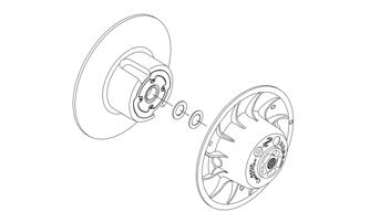
2.Install the movable sheave onto the driven shaft until it is fully seated onto the splines of the shaft; then install the offset shims and the stationary sheave.
SNO-547
3.Secure the sheaves using the existing cap screw and washer making sure the washer is cupped toward the sheave. Tighten to 60 ft-lb.
SNO-544
4.Install the drive belt; then check drive clutch/driven clutch alignment.
CAUTION
Make sure the drive belt is installed after the driven clutch is completely installed and torqued to 60 ft-lb. Failure to do this will cause damage to the driven clutch.
Drive Clutch/Driven Clutch
If premature drive belt wear is experienced or if drive belt turns over, check parallelism/offset. Also, parallelism/offset must be checked whenever either drive clutch or driven clutch is serviced. To check offset, use appropriate Clutch Alignment Bar. To check parallelism, use Parallelism Bar.
CHECKING OFFSET NOTE: The drive belt does not need to be removed
to check offset.
1.Set the brake lever lock; then remove the left-side access panel. 2.Place Alignment Plug into the bore of the drive clutch; then place Alignment Bar onto the stationary sheave of the driven clutch and into the groove of the alignment plug.
SNO-578
NOTE: Make sure the alignment bar is positioned
over the driven clutch cap screw.
3.If the offset is correct (1.530”), the line on the alignment bar will be aligned with the outside of the alignment plug. If not, proceed to Adjusting Offset.
SNO-579
NOTE: To achieve proper offset (1.530”), the driven
clutch cap screw and washer must to be installed and tightened to 60 ft-lb.
CORRECTING OFFSET 1.Thread Belt Removal/Installation Tool clockwise into the driven clutch until the movable sheave opens far enough to remove the drive belt. Remove the belt and the tool.
0749-025
2.Remove the cap screw and washer securing the driven clutch to the driven shaft; then remove the stationary sheave from the shaft. 3.To move the stationary sheave inward on the shaft, remove alignment washers located on driven shaft. 4.To move the stationary sheave outward on the shaft, add alignment washers to the driven shaft. NOTE: Available shim washers from Arctic Cat are
p/n 0648-850 (0.090 in.) and (p/n 0648-849 (0.030 in.). When adding or removing washers, the thickest washer in the stack needs to be the most inward on the shaft.
5.Arrange washers to obtain the correct offset; then install stationary sheave and secure using the cap screw and washer. Tighten to 60 ft-lb. 6.Install the drive belt.
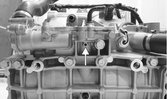
REMOVING CHAIN CASE/DRIVEN SHAFT/DRIVESHAFT/TRACK (ZR/XF/Pantera/Norseman) 1.Remove the left- and right-side panels, hood. 2.Remove the drive and driven clutches.
3.Remove the screws securing the PTO engine mount plate to the engine and the chassis. 4.Remove the expansion chamber and the resonator; then remove the right-side footrest. 5.Disconnect the speed sensor connector and the oil level connector.
6.Place a drain pan under the chain case; then loosen the eleven screws securing the chain case cover/oil tank assembly to the chain case housing starting with the bottom screws first.
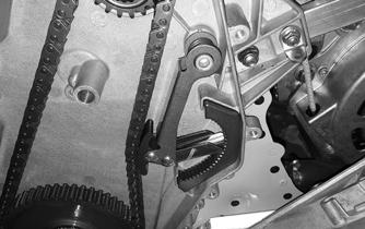
7.Remove the chain case cover/oil tank and set out of the way leaving the oil hose connected. 8.Release tension on the chain tensioner; then remove the ratchet block and the tensioner.
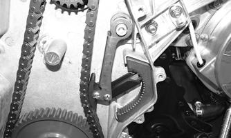
XM385
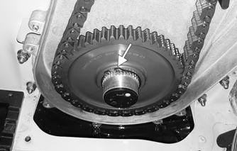
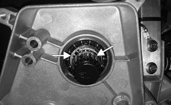
9.Remove the retaining ring securing the upper sprocket to the driven shaft.
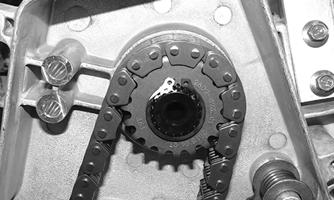
XM386
10.Remove the retaining ring securing the lower sprocket. Remove the sprockets and chain.
XM387
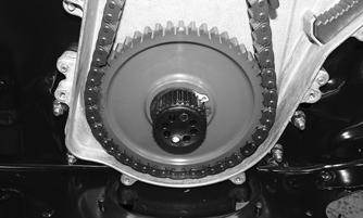
11.Remove the inner black retaining ring; then remove the retaining ring and washer securing the driven shaft.
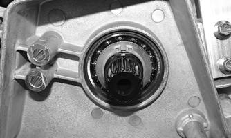
XM389
XM388
12.Once the snap ring and washers have been removed from the driven shaft, the shaft may be removed from the chassis.
13.Remove the skid frame assembly. 14.Remove the brake shield and the left-side footrest.
NOTE: DO NOT split the brake caliper unless nec-
essary service work is required.
15.Remove the cap screws securing the inner caliper to the tunnel; then remove the caliper and the driveshaft assembly.
PC148A
NOTE: If the caliper will not slide off the driveshaft
easily, proceed to step 17.
16.Remove the retaining pin and the brake disc pads; then pump the brake lever 3 or 4 times then pull back and secure the lever to the handlebar using a cable tie. This will keep the fluid from leaking. NOTE: Place an absorbent towel under the caliper
to absorb slight amount of brake fluid. Do not compress the brake lever.
17.Remove the retaining ring securing the brake disc to the driveshaft and remove the brake disc.
NOTE: It may be necessary to use Brake Caliper
Bearing Puller to remove the caliper/bearing assembly.
NOTE: If the chain case needs to be removed,
remove all machine screws with lock nuts.
CLEANING AND INSPECTING CHAIN CASE 1.Inspect sprockets and chain for excessive wear or stretching. 2.Inspect bearings and sprockets for roughness or chipping. NOTE: If bearing replacement is necessary, the
chain case must be removed from the tunnel and an appropriate press utilized to remove and install bearings.
3.Clean all interior chain case surfaces and components in cleaning solvent and dry using compressed air.
! WARNING
Always wear safety glasses when using compressed air.
ASSEMBLING/INSTALLING CHAIN CASE/DRIVEN SHAFT/DRIVESHAFT/ TRACK (ZR/XF/Pantera/Norseman) If the driveshaft and driven shaft were not removed, proceed to step 12. 1.Install chain case assembly onto the chassis and secure with the machine screws and four lock nuts.
Tighten the self-tapping screws to 12 ft-lb and the existing screws and nuts to 10 ft-lb.
SNO-765
2.Place the driveshaft/drive sprocket assembly into the tunnel brake-end first; then into the chain case driveshaft bearing. 3.Install the inner brake caliper assembly and secure with three cap screws and the retaining ring. Tightened cap screws (threads coated with blue Loctite #243) securely.
PC148A
NOTE: If the brake caliper was split, proceed to
step 4. If not, proceed to step 6.
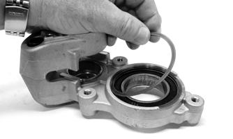
4.Install the brake disc and secure with the retaining ring. 5.Making sure the seal is correctly installed in the outer brake caliper, install on the inner caliper and secure with two cap screws. Tighten to 25 ft-lb.
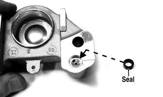
PC173A
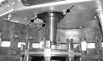
7.Install the brake shield and left-side footrest. Tighten the shield cap screws to 8 ft-lb. 8.Install the driven shaft w/mount plate from the left-side; then secure the PTO-side engine mounting plate to the crankcase with the existing cap screws (coated with blue Loctite #243) and washers. Tighten to 25 ft-lb.
XM465
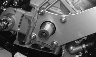
9.Secure the plate to the driven shaft bearing hub using the existing cap screws (coated with blue Loctite #243). Tighten to 14 ft-lb. Secure the plate to the chassis using the existing cap screw (coated with blue Loctite #243). Tighten to 25 ft-lb.
XM466
10.Install the drive clutch and tighten the clutch cap screw w/washer to 51 ft-lb; then install the driven clutch and drive belt. Tighten to 20 ft-lb. 11.Install the existing washers; then press in on the driven shaft and secure the shaft using the existing washer and snap ring.
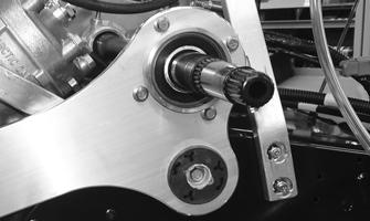
XM388
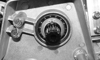
12.Install the black snap ring onto the inner snap ring groove in the driven shaft.
XM389
13.Install the sprockets and chain onto the driveshaft and driven shaft and secure using the existing snap rings.
XM387
XM386
14.Install the ratchet block and tensioner; then set the tensioner in the fifth notch in the block as it is self tightening.
15.Install the chain case cover/oil tank assembly and secure with the existing screws (threads coated with blue Loctite #243). Tighten in a crisscross pattern to 12 ft-lb. Fill the chain case with 15 oz. of Arctic Cat
Chain Lube.
16.Connect the speed and oil sensor connector. 17.Install the right-side footrest support and secure to the belly pan using the existing screws. 18.Install the resonator.
19.Secure the lower console to the skid panels; then install the hood and both access panels.
REMOVING CHAIN CASE/DRIVEN SHAFT/DRIVESHAFT/TRACK (M) 1.Remove the left- and right-side panels and the hood. 2.Remove the drive and driven clutches.
3.Remove the screws securing the PTO engine mount plate to the engine and the chassis. 4.Remove the expansion chamber and the resonator; then remove the right-side footrest. 5.Disconnect the speed sensor connector, the oil pump connector, and the oil level connector.
XM574
10.Remove the retaining ring securing the upper sprocket to the driven shaft.
XM572

11.Remove the retaining ring securing the lower sprocket. Remove the sprockets and chain.
XM576
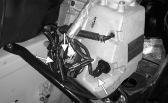
6.Disconnect the three oil hoses from the oil tank and from the oil pump.
XM577
7.Place a drain pan under the chain case; then loosen the eleven screws securing the chain case cover/oil tank assembly to the chain case housing starting with the bottom screws first.
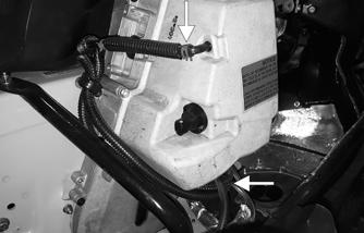
XM573
12.Remove the inner black retaining ring; then remove the retaining ring and washer securing the driven shaft.
XM575
13.Once the snap ring and washers have been removed from the driven shaft, the shaft may be removed from the chassis.
14.Remove the skid frame assembly. 15.Remove the brake shield and the left-side footrest; then remove the two nuts securing the driveshaft using the brake disc socket (p/n 0644-481).
XM578
NOTE: DO NOT split the brake caliper unless nec-
essary service work is required.
16.Remove the cap screws securing the caliper to the tunnel; then remove the caliper and the driveshaft assembly.
XM579
NOTE: If the chain case needs to be removed,
remove all machine screws with lock nuts.
CLEANING AND INSPECTING CHAIN CASE 1.Inspect sprockets and chain for excessive wear or stretching. 2.Inspect bearings and sprockets for roughness or chipping. NOTE: If bearing replacement is necessary, the
chain case must be removed from the tunnel and an appropriate press utilized to remove and install bearings.
3.Clean all interior chain case surfaces and components in cleaning solvent and dry using compressed air.
! WARNING
Always wear safety glasses when using compressed air.
ASSEMBLING/INSTALLING CHAIN CASE/DRIVEN SHAFT/DRIVESHAFT/ TRACK (M) If the driveshaft and driven shaft were not removed, proceed to step 12. 1.Install chain case assembly onto the chassis and secure with the machine screws and four lock nuts.
Tighten the self-tapping screws to 12 ft-lb and the existing screws and nuts to 10 ft-lb.
SNO-765
2.Place the driveshaft/drive sprocket assembly into the tunnel brake-end first; then into the chain case driveshaft bearing. 3.Position the brake caliper, bushing, and brake disc onto the driveshaft.
4.Secure the brake caliper to the tunnel using the existing three cap screws. Tighten to 21 ft-lb (threads coated with blue Loctite #243).
XM579
5.Thread the first nut onto the drive shaft; then using the brake disc nut tool, tighten the nut to 100 ft-lb.
Thread the second nut onto the drive shaft and tighten against the first nut to 100 ft-lb.
XM466
10.Install the drive clutch and tighten the clutch cap screw w/washer to 51 ft-lb; then install the driven clutch and drive belt. Tighten to 20 ft-lb. 11.Install the existing washer; then press in on the driven shaft and secure the shaft using the existing washer and snap ring. 12.Install the black snap ring onto the inner snap ring groove in the driven shaft.
XM578
6.Install the skid frame.
7.Install the brake shield and left-side footrest. Tighten the shield cap screws to 8 ft-lb. 8.Install the driven shaft w/mount plate from the left-side; then secure the PTO-side engine mounting plate to the crankcase with the existing cap screws (coated with blue Loctite #243) and washers. Tighten to 25 ft-lb.
XM575
13.Install the sprockets and chain onto the driveshaft and driven shaft and secure using the existing snap rings.
XM465
9.Secure the plate to the driven shaft bearing hub using the existing cap screws (coated with blue Loctite #243). Tighten to 14 ft-lb. Secure the plate to the chassis using the existing cap screw (coated with blue Loctite #243). Tighten to 25 ft-lb.
XM573
Drive Sprockets
REMOVING NOTE: The drive sprockets must be removed from
the brake side.
XM572
14.Install the ratchet block and tensioner; then set the tensioner in the fifth notch in the block as it is self tightening.
XM574
15.Install the chain case cover/oil tank assembly and secure with the existing screws. Tighten in a crisscross pattern to 108 in.-lb. Fill the chain case with 15 oz. of Arctic Cat Chain Lube.
16.Connect the oil hoses to the oil tank and the oil pump and secure using the clamps; then connect the speed, oil pump, and the oil sensor connectors.
YM-075A
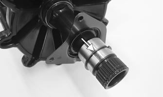
1.Remove the snap ring on the brake side of the driveshaft; then remove the retaining plate seal.
YM-074A
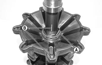
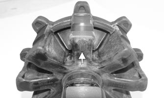
2.For installing purposes, scribe a line on the driveshaft (A) next to the drive sprocket for proper alignment; then scribe a line on the driveshaft directly in line with the timing arrows (B located on the inside of the sprockets) on the drive sprockets for proper sprocket timing.
XM576
17.Install the right-side footrest support and secure using the existing screws. 18.Install the resonator and the expansion chamber. 19.Install the hood and both access panels.
YM-071A
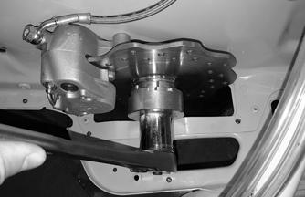
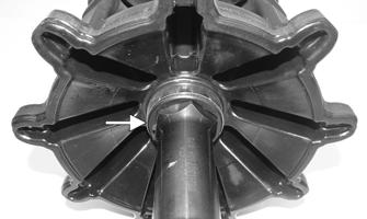
3.Using a suitable press positioned against the tension-collar of the drive sprocket (located on the gear case) and of the driveshaft, press the drive sprockets off the driveshaft.
CAUTION
Always press against the tension-collar of the drive sprockets or damage to the components will occur.
YM-069A
CLEANING AND INSPECTING 1.Thoroughly wash all metallic components in parts-cleaning solvent. Dry using compressed air. 2.Wash all non-metallic components with soap and water.
3.Inspect the driveshaft for damaged splines or stripped threads. 4.Inspect the seals for any breaks or damage. 5.Inspect the track for cuts, gouges, or wear. 6.Inspect the brake disc for wear or cracks. 7.Inspect the track drive sprockets for wear or damage.
INSTALLING NOTE: The drive sprockets must be installed from
the brake side.
YM-075B
NOTE: Prior to installing the sprockets onto the
driveshaft, lightly chamfer the inside edge of the sprocket to avoid binding.
1.Properly align the scribed line (B) on the driveshaft (from removing) with the timing arrow on the drive sprocket; then slide the sprocket onto the driveshaft as far as it will go.
YM-071A
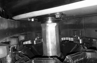
2.Using a suitable press and fixture, press the driveshaft into the sprocket until it aligns with the line scribed in removing. 3.Slide the remaining sprocket onto the driveshaft making sure the timing arrow/lines (from removing) are aligned; then using the press/fixture, press the sprocket to the remaining alignment line.
CAUTION
Always press against the tension-collar of the drive sprockets or damage to the components will occur.
NOTE: When pressing new sprockets on the drive-
shaft, align the sprocket alignment marks or the sprockets won’t be timed correctly.
YM-072A
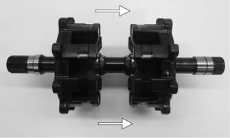
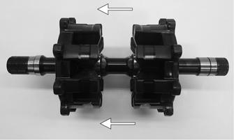
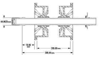
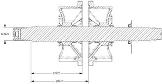
4.Using a calipers, measure distances between the sprockets and from the sprockets to each end of the driveshaft for proper location.
0749-790
0752-837
5.Install the seal retaining plate; then install the existing snap ring.
XM283A
Track Tension
CHECKING
! WARNING
DO NOT attempt to check or adjust track tension with engine running. Turn ignition key to the OFF position. Personal injury could result from contact with a rotating track.
1.Remove excess ice and snow buildup from the track, track drive sprockets, and the inside of the skid frame.
2.Elevate the snowmobile on a shielded safety stand high enough to use a spring scale. 3.At mid-point of the track (on the bottom side), hook a spring scale around a track clip; then pull down on the scale to the recommended pressure. Measure the deflection (distance) between the bottom of the wear strip and the inside surface of the track clip. Compare the measurement with the chart in the General
Information section.
NOTE: Measurement is from the bottom of the
wear strip at the point of the shock pad on the slide rail.
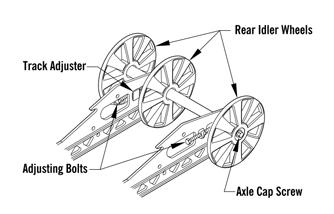
ADJUSTING NOTE: To ensure proper track tension adjustment,
perform all adjustments on both sides of the snowmobile.
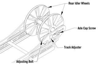
1.Loosen the idler wheel axle cap screws.
ZR/XF/Pantera/Norseman
0752-479
XF HC/M
0752-481
Alpha One
0752-480
2.If the deflection (distance between the bottom of the wear strip and the inside surface of the track clip) exceeds specifications, tighten the adjusting bolts to take up excessive slack in the track. 3.If the distance between the bottom of the wear strip and the inside surface of the track clip is less than specified, loosen the adjusting bolts to increase the slack in the track.
CAUTION
Always maintain track tension within recommended specification.
5.After proper track tension is obtained, tighten the idler wheel axle cap screws to 34 ft-lb. NOTE: Since track tension and track alignment are
interrelated, always check both even if only one adjustment seems necessary.
! WARNING
Always make sure the adjusting bolts are snug against the axle and the idler wheel cap screws. Failure to do so could cause the track to become extremely loose and, under some operating conditions, allow the idler wheels to climb over the track lugs forcing the track against the tunnel causing the track to “lock.” If a track “locks” during operation, severe personal injury could result.
Track Alignment
NOTE: There is no track alignment with the Alpha
One skid frame assembly.
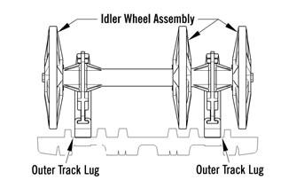
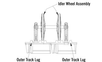
NOTE: Proper track alignment is when the rear
idler wheels are equidistant from the inner drive lugs on the inside surface of the track.
CHECKING/ADJUSTING ! WARNING
Make sure the ignition key is in the OFF position and the track is not rotating before checking or adjusting track alignment. Personal injury could result if contact is made with a rotating track.
1.Remove excess ice and snow buildup from the track, track drive sprockets, and the inside of the skid frame.
2.Position the tips of the skis against a wall; then using a shielded safety stand, raise the rear of the snowmobile off the floor making sure the track is free to rotate.
3.Start the engine and accelerate slightly. Use only enough throttle to turn the track several revolutions.
SHUT ENGINE OFF.
! WARNING
The tips of the skis must be positioned against a wall or similar object for safety. Keep hands, feet, and clothing away from moving components.
! WARNING
DO NOT stand behind the snowmobile or near the rotating track. NEVER run the track at high speed when the track is suspended.
NOTE: Allow the track to coast to a stop. DO NOT
apply the brake because it could produce an inaccurate alignment condition.
4.When the track stops rotating, check the relationship of the rear idler wheels and the inner track drive lugs.
If the rear idler wheels are centered between the inner track drive lugs, no adjustment is necessary. If not, proceed to step 5.
ONS-062
XF HC/M
0752-482
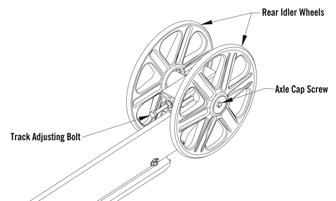
5.On the side of the track which has the inner track drive lugs closer to the rear idler wheel, loosen the idler wheel axle cap screw; then rotate the adjusting bolt clockwise 1 to 1 1/2 turns.
ZR/XF/Pantera/Norseman
0752-479
XF HC/M
6.Check the track alignment and make the necessary adjustments until proper alignment is obtained. NOTE: Make sure correct track tension is main-
tained after adjusting track alignment.
7.After proper track tension and alignment are obtained, tighten the idler wheel axle cap screw to 34 ft-lb; then tighten the adjusting bolt to 84 in.-lb. ! WARNING
Always make sure the adjusting bolts are snug against the axle and the idler wheel cap screws. Failure to do so could cause the track to become extremely loose and, under some operating conditions, allow the idler wheels to climb over the track lugs forcing the track against the tunnel causing the track to “lock.” If a track “locks” during operation, severe personal injury could result.
NOTE: Field test the track under actual conditions
and after the field test, check track alignment and track tension; adjust as necessary.
Brake System
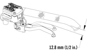
CHECKING BRAKE LEVER TRAVEL 1.Compress the brake lever fully. NOTE: Do not pump the brake lever as it will pro-
duce an inaccurate reading.
2.Measure the distance between the brake lever and the handlebar. The distance must be greater than 1/2in.
0752-475
3.If the distance is less than specified, check the brake fluid level, inspect for leakage, and check the brake pads.
! WARNING
Do not operate the snowmobile if the distance between the compressed brake lever and handlebar is less than 1in. Brake loss may occur. Brake loss can result in severe personal injury.
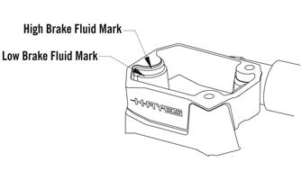
CHECKING AND ADDING BRAKE FLUID 1.With brake fluid reservoir in a level position and the cover removed, check the fluid level. The brake fluid level must be at the high mark in the reservoir.
0752-476
2.If the brake fluid level is low, add Arctic
Cat-approved brake fluid until the fluid is at the recommended level. Install and secure the reservoir cover. DO NOT allow moisture to contaminate the brake system.
CAUTION
Brake fluid is highly corrosive. Do not spill brake fluid on any surface of the snowmobile.
! WARNING
Do not overfill the brake fluid reservoir. Overfilling the reservoir may cause the brake system to hydraulically lock. Use only approved brake fluid. Never substitute or mix different types or grades of brake fluid. Brake loss may occur. Brake loss can result in severe injury or even death.
CHANGING BRAKE FLUID The brake fluid must be changed on a regular basis and/or whenever the brake fluid has been overheated or contaminated. The brake fluid should be changed every 1000 miles or at the end of the snowmobiling season, whichever occurs first.
Arctic Cat recommends the removal and disassembly of the brake caliper assembly when changing the brake fluid.
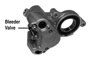
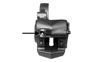
1.Slide a piece of flexible tubing over the ball of the bleeder valve and direct the other end into a container. CAUTION
Brake fluid is highly corrosive. Do not spill brake fluid on any surface of the snowmobile.
! WARNING
Use only DOT 4 or DOT 5 brake fluid. Any substitute may result in a loss of brakes.
PC223A
2.Slowly compress the brake lever and hold. Open the bleeder valve to release the fluid; then compress the brake lever repeatedly until all brake fluid is expelled. Close the bleeder valve. 3.Add new approved brake fluid to the reservoir; then compress the brake lever and hold. Open the bleeder valve. Repeat the compression until brake fluid flows free of air bubbles and appears clean. NOTE: It may be necessary to refill the reservoir a
number of times to eliminate all air bubbles in the system.
4.When the brake fluid is free of all air and the brake lever feels firm when compressed, fill the reservoir; then install and secure the cover. Remove the tube from the bleeder valve.
5.Bleed the brake system (see Bleeding Brake System in this sub-section).
BLEEDING BRAKE SYSTEM If the brake lever feels spongy when applied, the brake system may need to be bled. 1.With the handlebar in the highest position, remove the reservoir cover and fill the reservoir with approved brake fluid.
2.Slide a piece of flexible tubing over the ball of the bleeder valve and direct the other end into a container. CAUTION
Brake fluid is highly corrosive. Do not spill brake fluid on any surface of the snowmobile.
! WARNING
Use only approved brake fluid. Any substitute may result in a loss of brakes.
! WARNING
Do not use brake fluid from a container opened for a long period of time. Unsealed brake fluid containers will absorb moisture and can contaminate the fluid inside.
PC223A
3.Slowly compress the brake lever and hold. Open the bleeder valve to release the fluid and air. When the fluid stops flowing, close the bleeder valve; then release the brake lever.
4.Repeat step 3 until the brake fluid flows free of air bubbles.
NOTE: It may be necessary to refill the reservoir
during the bleeding process.
5.When the brake fluid is free of all air and the brake lever feels firm when compressed, fill the reservoir; then install and secure the cover. Remove the tube from the bleeder valve.
CHECKING AND REPLACING BRAKE PADS 1.Remove the brake shield; then remove the retaining pin securing the brake pads.
ZR-273
2.Remove one brake pad and measure the thickness.
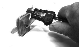
NOTE: Brake pad thickness must be greater than
0.20 in. If brake pad thickness is less than specified, replacement of both pads is necessary. Always replace with new pads and always replace as a set.
3.Position the new brake pad into the caliper. 4.Repeat for the other pad; then secure the pads with the retaining pin. NOTE: When new brake pads are installed, a “bur-
nishing” process is required. Drive the snowmobile slowly and compress the brake lever several times until the pads just start to warm up; then allow them to cool down. This procedure stabilizes the pad material and extends the life of the pads.
BRAKE CALIPER/BRAKE DISC/DRIVESHAFT BEARING Removing/Disassembling 1.Remove both access panels; then remove the drive belt and driven clutch.
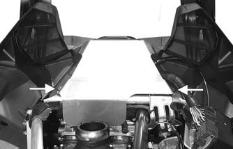
2.Remove the screws securing the brake shield and footrest to the chassis.
3.Slide a piece of flexible tubing over the ball of the bleeder valve and direct the other end into a container.
PC223A
CAUTION
Brake fluid is highly corrosive. Do not spill brake fluid on any surface of the snowmobile.
4.Open the bleeder valve and compress the brake lever several times to drain the reservoir of fluid.
5.Remove the brake hose from the caliper. Use an absorbent towel to collect any remaining brake fluid. 6.Remove the retaining pin securing the brake pads; then remove both pads.
ZR-273
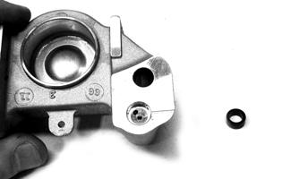
NOTE: If servicing the brake disc only, remove the cap screws securing the caliper housings together; then remove the outside housing. Account for the seal.
NOTE: To aid in removing the inner caliper hous-
ing, completely loosen track tension.
CAUTION
If the caliper housings are to be separated, take care not to allow any contaminants into the fluid passages of the calipers.
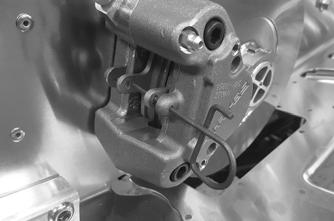
7.Remove the retaining ring from the driveshaft and remove the brake disc; then remove the cap screws securing the inner caliper/driveshaft bearing housing to the chassis.
PC148A
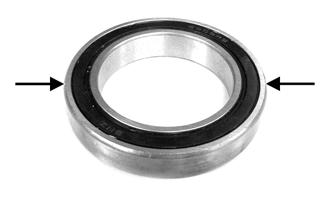
8.If the bearing will be replaced, remove the retaining ring; then using a suitable press, remove the bearing from the housing.
NOTE: Never reuse bearings that have been
removed. Always use new bearings.
NOTE: If the caliper housings were separated, they
must be secured together with the seal installed between the inner and outer housings.
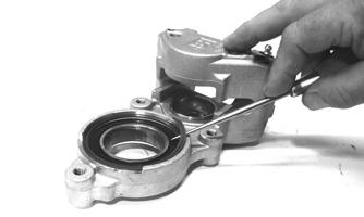
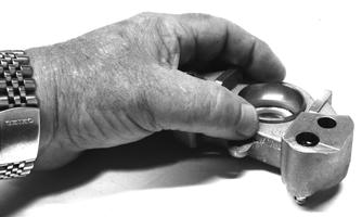
9.Position a piece of wood between the pistons. Using low-pressure compressed air, blow into the caliper brake hose fitting to loosen the brake pistons. ! WARNING
Always wear safety glasses when using compressed air.
PC221A
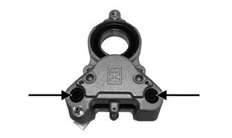
10.Remove the two screws securing the caliper halves.
Discard the seal.
PC219A
PC173
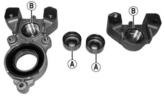
11.Remove the pistons (A) and O-rings (B); then discard the O-rings.
PC220A
Cleaning and Inspecting 1.Inspect the brake pistons for gouges, cracks, pitting, scuffing, or corrosion. If any of these conditions exist, replace the piston. NOTE: The inner and outer caliper housings are
not serviceable components. If either or both are defective or damaged, the complete caliper assembly must be replaced.
2.Clean the piston outer surface by using a soft
Scotch-Brite pad and clean brake fluid as a cleaner.
3.Inspect the piston bore of the inner and outer brake calipers for gouges, cracks, pitting, scuffing, or corrosion. If any of these conditions exist, replace the caliper. 4.Clean the caliper inner wall surface using a soft lint-free cloth and clean brake fluid.
5.Inspect the condition of the brake pads. Replace if damaged or worn. The brake pad thickness must be greater than 0.20 in. If the brake pad thickness is less than specified, replacement of both pads is necessary. 6.Inspect the brake hose for cracks and deterioration and check the condition of the threaded connectors.
Assembling/Installing 1.Apply approved brake fluid to new O-rings; then install the O-rings into the groove of each caliper half.
2.In each caliper half, apply approved brake fluid to the brake piston; then while twisting, install the piston with the dished side facing out.
CAUTION
Do not use any sharp cleaning tool on the piston surface or in the O-ring groove as it may cause damage.
CAUTION
Care must be taken not to allow any contaminants into the fluid passages of the calipers or brake system malfunction may occur.
CAUTION
Never reuse piston O-rings. Always install new O-rings when installing pistons in the brake caliper.
PC201
NOTE: To aid in installing the piston, make sure the
piston O-ring is properly seated in the groove of the caliper housing.
3.Using a suitable press, install a new inner bearing into the caliper housing until it is properly seated.
CAUTION
When installing a bearing, always press on the outer race of the bearing.
ZJ239A
4.Install the snap ring securing the bearing in the caliper housing.
PC204
5.Place the inner caliper housing/driveshaft bearing housing onto the driveshaft and secure with the cap screws coated with blue Loctite #243. Tighten to 25 ft-lb.
6.Apply Anti-Seize Thread Compound to the splines of the brake disc; then install on the driveshaft and secure with the retaining ring. 7.Install a new seal in the outer caliper fluid passage; them install the outer caliper and secure with the cap screws. Tighten to 25 ft-lb.
PC173A
8.Install new brake pads in the caliper and secure with the retainer pin. 9.Bleed the brake system (see Bleeding Brake System in this sub-section). 10.Install the brake shield and footrest; then install the drive belt (see Drive Belt in this section) and driven clutch. Tighten the driven clutch cap screw to 60 ft-lb.
11.Adjust the track tension (see Track Tension in this section) and track alignment (see Track Alignment in this section). 12.Close and secure both side panels.
Brake Lever/Master Cylinder Assembly
REMOVING 1.Slide a piece of flexible tubing over the ball of the bleeder valve and direct the other end into a container.
PC223A
2.Remove the two screws securing the reservoir cover and remove the reservoir cover; then open the bleeder valve. Allow the brake fluid to drain completely.
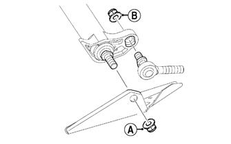
3.Place an absorbent towel around the connection to absorb brake fluid. Remove the banjo-fitting bolt (A) securing the brake fluid hose (B) to the master cylinder. Discard the two crush washers.
CAUTION
Brake fluid is highly corrosive. Do not spill brake fluid on any surface of the snowmobile.
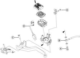
ONS-104
4.Remove the pin (C) securing the brake lever to the master cylinder. 5.Using a small screwdriver, compress the tabs of the brake light switch (D) to release it from the master cylinder. 6.Remove the Torx-head screw (E) securing the brake reservoir to the handlebar; then place a towel over the reservoir and remove the assembly from the handlebar.
INSPECTING 1.Inspect the snap ring and pin securing the brake lever for wear or damage; then inspect the brake lever for cracks or damage. 2.Inspect the master cylinder reservoir and cover for cracks and leakage. NOTE: The master cylinder is a non-serviceable
component. If any wear or damage is detected, the master cylinder must be replaced.
3.Inspect the brake fluid hose for cracks, deterioration, and the condition of the fittings (threaded and compression).
INSTALLING 1.Position the brake assembly on the handlebar. Secure with the Torx-head screw (E); tighten to 80 in.-lb. 2.Install the brake fluid hose (B) to the master cylinder with the banjo-fitting bolt (A) and two new crush washers. Tighten to 20 ft-lb.
3.Install the brake light switch (D) to the master cylinder.
4.Install the brake lever; then secure with pin (C). 5.Place the reservoir cover onto the reservoir; then secure with the three screws. Tighten evenly to 6-8 in.-lb.
6.Bleed the brake system (see Bleeding Brake System in this sub-section).
CAUTION
Always use new crush washers when installing the brake fluid hose.
Troubleshooting Hydraulic Brake System
Troubleshooting Track
Problem: Caliper Leaks Condition Remedy
1. Caliper O-ring deteriorated — severed 1.Replace O-ring 2. Piston — O-ring damaged 2.Repair piston — replace piston — O-ring
Problem: Lever Spongy — Bottoms Out Condition Remedy
1. Brake system air bubbles present 1.Bleed brake system 2. Master cylinder damaged — faulty 2.Replace master cylinder
Problem: Oscillation Feedback in Lever Condition Remedy
1. Brake pad residue present on brake disc 1.Replace pads — clean disc 2. Caliper loose 2.Tighten mounting bolts
Problem: Loss of Brake Condition Remedy
1. Brake fluid overheated — contaminated 1.Replace fluid 2. Master cylinder damaged — faulty 2.Replace master cylinder 3. Caliper — brake hose leaking 3.Replace caliper O-ring — repair piston — replace piston — O-ring — brake hose 4. Brake lever linkage damaged 4.Repair — replace lever — mounting bolt
Problem: Brakes Drag Condition Remedy
1. Master cylinder damaged — faulty 1.Replace master cylinder 2. Brake pads worn — tapered 2.Replace pads
Problem: Snowmobile Won’t Stop — Have to Pull Too Hard on Lever Condition Remedy
1. Pads/brake disc glazed 1.Replace pads — clean disc 2. Brake lever binding 2.Loosen pivot bolt — replace master cylinder 3. Caliper pistons binding 3.Service caliper assembly
Problem: Track Edge Frayed — Drive Lugs Worn Condition Remedy
1. Track alignment adjusted incorrectly 1.Align — replace track
Problem: Track Worn Adjacent to Outer Drive Lugs Condition Remedy
1. Track tension adjusted incorrectly 1.Adjust track tension 2. Rear idler wheels dirty — damaged 2.Clean — replace idler wheels
Problem: Track Ratchets — Slaps Tunnel Condition Remedy
1. Track tension adjusted incorrectly (too loose) 1.Adjust track tension (tighten) 2. Drive sprockets misaligned — damaged 2.Align — replace sprockets
Problem: Wear-Strip Wear Excessive Condition Remedy
1. Slide rail bent — broken — damaged 1.Repair — replace slide rail 2. Track alignment adjusted incorrectly 2.Adjust track alignment
Troubleshooting Drive Clutch/Driven Clutch
Problem: Midrange Shift-Up (Too Quickly — Lowers RPM) Condition Remedy
1. Drive clutch spring weak 1.Replace drive clutch spring 2. Driven clutch spring weak 2.Replace driven clutch spring 3. Driven clutch spring preload tension inadequate 3.Replace driven clutch spring 4. Center-to-center distance too close 4.Adjust center-to-center distance 5. Driven clutch bearing worn — damaged 5.Replace bearing — movable sheave
Problem: Midrange Shift-Up (Too Slowly — Raises RPM) Condition Remedy
1. Drive clutch components dirty 1.Clean drive clutch components 2. Driven clutch components dirty 2.Clean driven clutch components 3. Driven clutch spring preload tension excessive 3.Replace driven clutch spring 4. Driven clutch bearing worn — dirty 4.Clean — replace bearing — movable sheave
Problem: Excessive Belt Deposits Condition Remedy
1. Offset/parallelism incorrect 1.Adjust offset/parallelism 2. Drive clutch/driven clutch sheaves rough — damaged — 2.Repair — replace — clean drive clutch/driven clutch dirty 3. Driven clutch movable sheave travel impaired 3.Service driven clutch 4. Driven clutch bearing worn — dirty 4.Clean — replace bearing — movable sheave
Problem: Excessive Belt Drag — Impaired Drive Clutch Disengagement Condition Remedy
1. Drive clutch components dirty — damaged 1.Clean — replace drive clutch components 2. Drive belt does not meet measurement specifications 2.Replace drive belt
Problem: Engine RPM Suddenly Increases — Drive Clutch Vibrates Condition Remedy
1. Cam arm pin bent — damaged 1.Replace pin 2. Cam arm damaged — broken 2.Replace cam arm 3. Drive clutch out of balance 3.Align — replace components — drive clutch — drive belt
Problem: Driven Clutch Vibrates Condition Remedy
1. Driven clutch out of balance 1.Service — replace driven clutch
Problem: Drive Clutch Engagement (Before Specified RPM) Condition Remedy
1. Drive clutch spring weak — bent 1.Replace spring 2. Cam arms incorrect — worn 2.Replace cam arms
Problem: Drive Clutch Engagement (After Specified RPM) Condition Remedy
1. Drive clutch spring incorrect 1.Replace spring 2. Spider buttons worn 2.Replace clutch
Problem: Drive Clutch Sticks Condition Remedy
1. Drive clutch components dirty 1.Clean drive clutch components 2. Movable sheave bent — binding 2.Clean — replace movable sheave 3. Spider buttons worn 3.Replace clutch
Problem: Drive Clutch Jerks — Shifts Erratically Condition Remedy
1. Drive clutch dirty 1.Clean — drive clutch components 2. Rollers worn 2.Replace clutch 3. Cam arms rough 3.Polish — replace cam arms 4. Spider buttons worn 4.Replace clutch 5. Sheaves dirty 5.Clean sheaves