50 minute read
Suspension

NOTE: Whenever a part is worn excessively,
cracked, or damaged in any way, replacement is necessary.
SPECIAL TOOLS A number of special tools must be available to the technician when servicing the rear suspension.
Description
Shock Absorber Air Pump Shock Absorber Air Pump (Dual Digital) Idler Wheel Puller Kit Rear Suspension Spring Tool Handlebar Stand Steering Post Stand
p/n
2603-614 0641-257 0644-570 0144-311 5639-152 5639-946
NOTE: Special tools are available from the Arctic
Cat Service Parts Department.
UNDERSTANDING THE SUSPENSION Quick acceleration and the ability to go through the turns with power are the most important handling qualities. This section explains how the skid frame functions to provide these two important handling qualities. Before proceeding, however, note these terms. Weight Transfer — A shift in the center of gravity in any direction depends on the force applied. Track Tension — The amount of tightness or looseness of the track when correctly mounted in the chassis. Spring Tension — The amount of force exerted on the spring by either fork tension adjustment or eye bolt adjustment. Ski Pressure — The amount of force exerted downward on the skis.
Good weight transfer characteristics are needed for fast acceleration (shift of weight from skis to track) and for cornering (shift of weight back to skis to hold the front end in turns). Effective weight transfer depends on suspension tension, position of rider, and the position of the front arm limiter.
To understand how the suspension system works, think of the entire system in terms of three points; the skid frame rear axle center, the skid frame front arm, and the ski saddle center.
Assume that the front arm functions as a stationary pivot point between the rear axle center and the ski saddle center. Also assume that the ski saddle center is the same height off the ground as the rear axle center. This produces the standard position arrangement. Under acceleration when the center of gravity is transferred to the rear of the machine, the rear suspension collapses slightly. This brings the rear arm point downward and with the front arm stationary, the teeter-totter effect reduces the pressure on the skis (position A). However, for controlled cornering, more pressure is needed on the skis. So when the driver decelerates coming into a corner, the center of gravity is transferred forward, putting the required pressure onto the skis and reducing the pressure on the rear suspension (position C).
0728-181
This is essentially what weight transfer is all about — the shift of weight to the rear of the machine for positive traction and good acceleration or to the front of the machine for positive handling and cornering control.
Suspension Setup Basics
SKI SHOCK ABSORBER SPRINGS The shock absorber springs have been matched to the shock valving and rear suspension. These springs are the result of hours of testing and comparison riding trying many different combinations of springs and shocks. If changes are necessary, several spring and shock sizes are available. While making these changes, keep the following points in mind:
Heavier/Stiffer Springs 1.These will require shocks with more rebound control, or the front end will become like a pogo stick. 2.Less aggressive steering in corners on deceleration, and less weight is transferred to the skis because of softer springs. 3.Less weight gets transferred to the rear of the snowmobile upon acceleration. NOTE: When stiffening the ski shock springs, also
stiffen the rear to match entire suspension.
Spring Tension Too Soft 1.Front end bottoms out; hard on front end parts. 2.With softer springs, the front end will become more aggressive in the corners as more weight will be transferred to the skis when decelerating. Also, more weight is transferred to the rear on acceleration and may can cause the front arm shock and spring to bottom out.
CAUTION
If the ski shock spring is adjusted too loose, the spring retainer may fall out. If the spring is adjusted beyond specification, the spring will coil bind and spring adjuster damage will occur.
ADJUSTING FOX iQS SHOCKS NOTE: If service work is needed on any FOX
shocks, the shock will have to be removed and sent to FOX or any FOX distributor for any service work. For FOX shock information, visit www.ridefox.com. Do not disassemble the stepper motor from the iQS shocks.
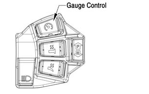
The iQS ski shocks, along with the rear skid iQS shock, are adjustable by the gauge control button on the handlebar.
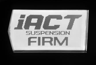
Approximately 5 seconds after the engine has started, the iACT Suspension Active screen will display briefly on the gauge, followed by the normal gauge display. This means the iACT suspension can be adjusted.

ZR-215
To adjust the suspension, press the CENTER of the gauge control button located on the left-side handlebar control. The iACT Suspension Active screen will briefly display; then the previously selected iACT suspension setting will display on the gauge.
ONS-068
The settings of Soft, Medium, or Firm can be achieved by then pressing the LEFT side or RIGHT side of the gauge control button. Once the desired setting is set, press the CENTER of the gauge control button to resume normal gauge display.
ZR-217

ZR-216
ZR-218
ADJUSTING SKI SHOCKS (FOX Float) The float shocks are individually adjustable for the terrain conditions and driving style of the operator. The ski shocks are initially preset at the factory (see the General Information section). However, the shocks can be “fine tuned” to match the operator’s weight, riding style, and terrain conditions.
NOTE: Care should be taken to have equal pressure
in the shocks before operating the snowmobile.
To increase or decrease air pressure, use the following procedure: NOTE: The shocks should not be under load when
adjusting.
NOTE: Adding air pressure will increase the air
spring force; reducing air pressure will decrease air spring force.
! WARNING
Do not exceed 10.5 kg/cm2 (150 psi) in the shock and 21 kg/cm2 (300 psi) in the EVOL (if equipped).
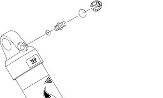
1.With all the weight removed from the front of the snowmobile, remove the air valve cap from the shock; then thread the valve of Shock Absorber Air
Pump onto the shock air valve approximately six rotations.
NOTE: As the pump is being attached to the shock,
the hose will fill with air resulting in a lower gauge pressure 0.14-3.52 kg/cm2 (2-5 psi).
2.To decrease air pressure in the shock, press the black bleed valve button half way down and hold until desired pressure is attained. NOTE: Pressing the button fully down and releasing
it will allow only a small amount of air to escape (micro-adjust).
3.To increase air pressure in the shock, pump until desired pressure is attained. 4.Remove the pump valve from the shock air valve. NOTE: As the pump valve is being removed from
the shock, the sound of air loss is from the pump hose, not from the shock.
5.Install the air valve cap onto the shock.
ADJUSTING REAR ARM SHOCKS (FOX Float) The float shock is adjustable for the terrain conditions and driving style of the operator. The shocks is initially preset at the factory. However, the shock can be “fine tuned” to match the operator’s weight, riding style, and terrain conditions.
To increase or decrease air pressure, use the following procedure: NOTE: The shock should not be under load when
adjusting. Raise the rear end of the snowmobile.
NOTE: Adding air pressure will increase the air
spring force; reducing air pressure will decrease air spring force.
! WARNING
Do not exceed 10.5 kg/cm2 (150 psi) in the shock and 21 kg/cm2 (300 psi) in the EVOL (if equipped).
1.With all the weight removed from the front of the snowmobile, remove the air valve cap from the shock; then thread the valve of Shock Absorber Air
Pump onto the shock air valve approximately six rotations.
NOTE: As the pump is being attached to the shock,
the hose will fill with air resulting in a lower gauge pressure 0.14-3.52 kg/cm2 (2-5 psi).
2.To decrease air pressure in the shock, press the black bleed valve button half way down and hold until desired pressure is attained. NOTE: Pressing the button fully down and releasing
it will allow only a small amount of air to escape (micro-adjust).
3.To increase air pressure in the shock, pump until desired pressure is attained. 4.Remove the pump valve from the shock air valve. NOTE: As the pump valve is being removed from
the shock, the sound of air loss is from the pump hose, not from the shock.
5.Install the air valve cap onto the shock.
FRONT ARM SPRING TENSION Having very light front arm spring tension is desirable. When riding in 4 in. or more of snow, the machine will be quicker if the front spring tension is adjusted lightly. If the spring tension is adjusted too stiff, the track angle at the front of the skid frame is steep. This steep angle prevents the snowmobile from getting up on plane and slows down by 5 to 8 mph. Also, the following could occur:
1.Slows machine down in loose snow.
2.Causes the snowmobile to dart and dive as a result of less track on the ground on deceleration. NOTE: A tight front arm works well under only two
conditions: sticky snow conditions in the spring of the year and in hill climbing on hard packed snow.
With the front arm adjusted too soft, the spring retainer may fall off of the spring. When riding in sticky snow (springtime or warm days) or hill climbing on hard snow, it may be desirable to stiffen the front arm spring tension. When this is done, weight is transferred back quicker. The problem with too much front arm spring tension is that the feel of the snowmobile becomes very short. The reason for this is the front arm becomes the pivot point between the spindles and rear of the snowmobile. With dominant spring tension on the front arm, the suspension is basically contacting the snow from a point below the front arm to the skis or the spindle pressure point. This makes for a very short and darting snowmobile on the trail. This is especially true when decelerating and the center of gravity is transferred forward.
A method for adjusting the front spring tension follows. NOTE: The spring tension should be set as soft as
possible when operating on trails and in deep snow.
0729-662
FRONT ARM LIMITER STRAPS Under no circumstances should the front arm limiter strap be lengthened. If lengthened, it may cause shock absorber travel problems. The two limiter straps can be shortened to suit driving style and some test driving time. With the rear arm in its present mounting location, no advantage has been noted from changing the strap length. If the front arm straps are shortened, the result will be more ski pressure and aggressive steering.
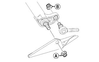
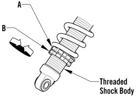
REAR ARM SHOCK SPRING (M/XF) Proper adjustment of rear arm shock absorber spring preload is necessary to get the most desirable ride. The rear arm shock spring is adjustable for the terrain conditions and driving style and weight of the operator. The spring adjuster nut has been set at the factory so the correct amount of threads are exposed between the adjuster nut and the threaded shock body as an initial setting. Rear spring preload adjustment is accomplished by loosening the adjuster nut locking collar (B) from the adjuster nut (A) and using the Spring Adjuster Tool from the tool kit, rotating the adjuster nut in whichever direction is desired. Tighten the locking collar against the adjuster nut.
0745-159
REAR ARM SPRING TENSION The rear spring tension is adjusted for the weight of the rider. Three possible adjustments exist: 1st block position — set for up to 150 lb 2nd block position — set for 150 to 200 lb 3rd block position — set for more than 200 lb
SNO-595
NOTE: When making any changes to the front or
rear suspension, the change should be made at both ends to keep the suspension balanced. For example, installing stiffer springs in front may require installing the next step stiffer spring in back to keep everything in balance.
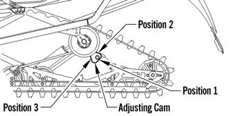
ADJUSTING REAR ARM COUPLER The rear arm coupler provides advantages over the standard suspension. First, with the coupler system, ski lift under acceleration is greatly reduced which provides improved handling. Second, when riding through rough terrain, the rear suspension arm receives some needed assistance from the front arm shock and spring as the rear arm is fully collapsed and locked up by the coupler blocks. The front arm then starts to collapse the shocks and spring which assist the rear springs. The result is a smoother ride for the operator. If additional coupler action is desired, the coupler blocks can be set to the number 2 or 3 position. Each of the coupler blocks has three positions numbered on the inside surface of the block. When changing the block position, change both to the same number. To make the coupler adjustment, follow the procedure below. 1.Loosen the two cap screws that secure the coupler blocks to the inside of the suspension rails. 2.Rotate the coupler blocks to the desired position making sure both are set the same.
0747-212
3.Place a 4-in. block of wood under the rear of the suspension just in front of the rear idler wheels to assist in collapsing the suspension. 4.Collapse the rear suspension until the rear arm is firmly against the coupler blocks aligning the two blocks squarely with the arm. While in this position, tighten the two cap screws securely.
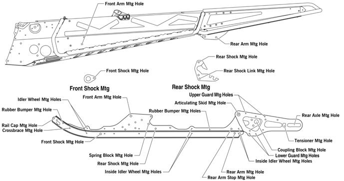
Chassis and Skid Frame Mounting Locations
All stock mounting locations must be used. If any alterations to the skid frame are made, shock absorber and suspension damage may occur.
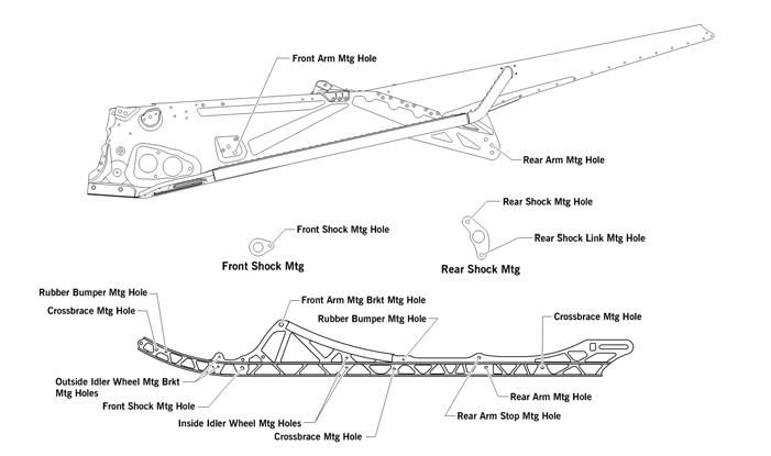
The suspensions have several possible mounting locations in the slide rails and tunnel. However, Arctic Cat recommends that when disassembling and assembling the suspension, all stock mounting locations be used as shown in the following illustrations:
129”/137” Models
0749-567
0750-524
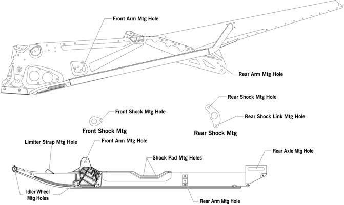
Alpha One Models
0752-694
0748-835
Norseman Models
0752-709
Servicing Suspension
This sub-section has been organized so each procedure can be completed individually and efficiently. NOTE: Some components may vary from model to
model. The technician should use discretion and sound judgment when removing and installing components.
NOTE: Whenever a part is worn excessively, cracked,
or damaged in any way, replacement is necessary.
Removing Skid Frame (Slide-Action Models)
NOTE: Many service procedures can be performed
without removing the skid frame. The technician should use discretion and sound judgment when removing and installing components.
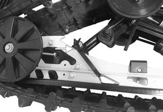
1.On iACT models, secure the rear arm forward to the slide rail using a suitable cable tie or strap to prevent the rear arm from collapsing rearward.
ZR-258
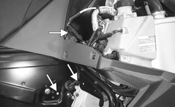
2.On iACT models, remove the right-side access panel; then remove the two screws and one nut securing the rear shock harness; then disconnect the harness from the suspension module harness.
ZR-259
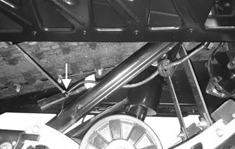
3.On iACT models, push the rear shock harness and grommet through the tunnel and secure to the front arm to prevent damage to the harness.
ZR-260
4.Remove the suspension springs from the blocks using the Rear Suspension Spring Tool. 5.Place a support stand under the rear bumper; then while holding the flared bushing, remove the rear arm assembly cap screws securing the skid frame to the tunnel.
NOTE: On models with tunnel flares, make sure
damage to the flares does not occur when the snowmobile is tipped onto the side.
6.Remove the support stand; then using an appropriate handlebar/steering post stand, tip the snowmobile onto one side.
7.Slide the skid frame rearward far enough to drop the front arm out of the slider axle; then remove the skid frame.
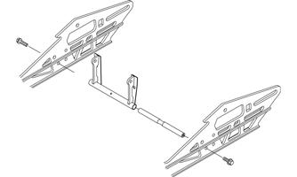
Removing Skid Frame (Float-Action Models)
NOTE: Many service procedures can be performed
without removing the skid frame. The technician should use discretion and sound judgment when removing and installing components.
1.Loosen the jam nuts and the track-tension adjusting bolts.
2.Place a support stand under the rear bumper; then while holding the flared bushing, remove the rear arm assembly cap screws securing the skid frame to the tunnel.
3.Remove the support stand; then using an appropriate handlebar/steering post stand, tip the snowmobile onto one side.
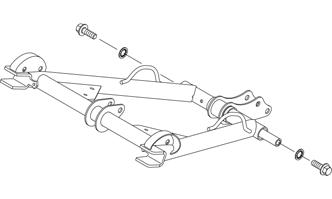
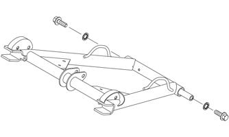
4.Remove the two cap screws and nuts securing the front of the skid frame to the chassis. Account for two washers.
5.On Alpha One models, remove the two cap screws while holding the two bushings on the inside of the tunnel. Account for two spacers, and both ice scratchers.
ONS-115
End Caps (Slide-Action)
REMOVING 1.Remove the lock nut and cap screw securing the end cap.
SNO-592
2.Using a hammer, tap the end cap off the rail.
CLEANING AND INSPECTING 1.Inspect the end cap area of the slide rail for cracks and wear.
2.Inspect the end cap for any signs of cracking or wear. 3.Clean both the slide rail area and the end cap. Using compressed air, clean the areas of dirt and gravel.
4.Inspect the cap screw for cracked, stretched, or damaged threads. Use a new lock nut when assembling.
! WARNING
Always wear an approved pair of safety glasses when using compressed air.
INSTALLING 1.Position the end cap on the slide rail; then align the hole in the end cap with the hole in the slide rail. 2.Secure with a cap screw, washers, and lock nut.
Tighten to 80 in.-lb.
End Caps (Float-Action)
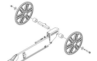
REMOVING 1.Remove the cap screws securing the end cap; then remove the idler wheel axle assembly from the rails.
Account for two end cap spacers.
SNO-694
2.Remove the snap rings securing the idler wheels to the axle; then using a rubber hammer, remove the wheels.
CLEANING AND INSPECTING 1.Inspect the end cap area of the slide rail for cracks and wear.
2.Inspect the end cap for any signs of cracking or wear. 3.Clean both the slide rail area and the end cap. Using compressed air, clean the areas of dirt and gravel.
4.Inspect idler wheel bearings. Remove as necessary.
! WARNING
Always wear an approved pair of safety glasses when using compressed air.
INSTALLING 1.Install the end cap spacers into the outside of the end caps; then install the end caps onto the axle assembly. 2.Install the idler wheel axle assembly onto the end of the rails. Secure using the existing cap screws (threads coated with blue Loctite #243). Tighten to 20 ft-lb.
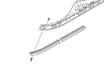
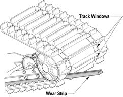
Wear Strips
REMOVING 1.Remove the machine screw and lock nut securing the wear strip to the front of the slide rail.
Wear Strips (Alpha One)
REMOVING 1.Remove the machine screws and lock nuts securing the wear strips to the rear of the slide rail.
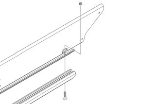
SNO-591
2.Align the wear strip with the openings (windows) in the track; then using a suitable driving tool, drive the wear strip rearward off the slide rail.
739-884A
CLEANING AND INSPECTING 1.Clean the slide rail using parts-cleaning solvent and compressed air.
2.Inspect the slide rail for cracks. If any cracks are found, replace the slide rail. 3.Using a straightedge, inspect the slide rail for any unusual bends. With the slide rail removed, place the straightedge along the bottom surface of the slide rail. If the rail is found to be bent, it must be replaced. ! WARNING
Always wear an approved pair of safety glasses when using compressed air.
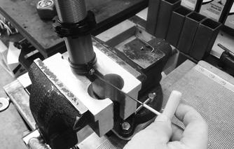
INSTALLING NOTE: Use a file to remove any sharp edges on the
lower portion of the rail.
1.Align the wear strip with the openings (windows) in the track and from the back, start the wear strip onto the rail; then using a block of wood and a hammer, drive the wear strip forward into position.
0752-763
2.Align the wear strips with the openings (windows) in the track; then using a suitable driving tool, drive the wear strip rearward off the slide rail.

0752-736
CLEANING AND INSPECTING 1.Clean the slide rail using parts-cleaning solvent and compressed air.
2.Inspect the slide rail for cracks. If any cracks are found, replace the slide rail. 3.Using a straightedge, inspect the slide rail for any unusual bends. With the slide rail removed, place the straightedge along the bottom surface of the slide rail. If the rail is found to be bent, it must be replaced. ! WARNING
Always wear an approved pair of safety glasses when using compressed air.
INSTALLING NOTE: Use a file to remove any sharp edges on the
lower portion of the rail.
1.Align the wear strip with the openings (windows) in the track and from the back, start the wear strip onto the rail; then using a block of wood and a hammer, drive the wear strip forward into position. 2.Secure with a machine screw and lock nut. Tighten to 50 in.-lb.
Shock Pads
REMOVING 1.Remove Torx-head screws and nuts securing the shock pads. 2.Remove the rear shock pads.
INSPECTING 1.Inspect the pads for damage or wear. 2.Inspect the rivet holes in the slide rail for damage or elongation.
INSTALLING 1.Place the pads brackets into position on the slide rail. 2.Secure the pads with existing Torx-head screws and nuts.
Idler Wheels/Mounting Blocks
REMOVING 1.Remove the cap screw and lock nut securing the idler wheel to the idler wheel mounting block; then remove the cap screw and lock nut securing the mounting block to the slide rail.
SNO-593
2.Account for a flat washer from the idler wheel cap screw.
CLEANING AND INSPECTING 1.Clean the bearing with a clean cloth. 2.Inspect each idler wheel for cracks or damage.
INSTALLING 1.Secure the mounting block on the slide rail with a cap screw and lock nut. Tighten to 10 ft-lb. NOTE: For proper alignment, install an idler wheel
cap screw into the top mounting block hole prior to tightening.
2.Place the idler wheel to the mounting block; then secure the idler wheel assembly with a cap screw, flat washer, and a lock nut. Tighten to 10 ft-lb.
Idler Wheels (Alpha One)
REMOVING 1.Remove and discard the cap screw and washer securing the idler wheel.
0752-775
CLEANING AND INSPECTING 1.Clean the bearing with a clean cloth. 2.Inspect each idler wheel for cracks or damage. 3.Rotate the idler wheel bearing (by hand) and inspect for binding or roughness.
INSTALLING 1.Place the idler wheel into position; then secure the idler wheel assembly with a new cap screw and flat washer. Tighten to 13 ft-lb.
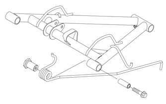
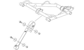
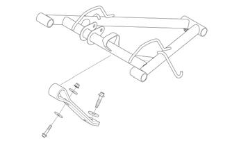
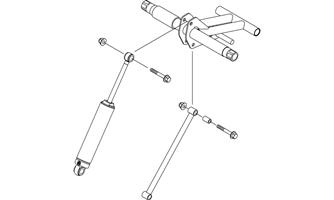
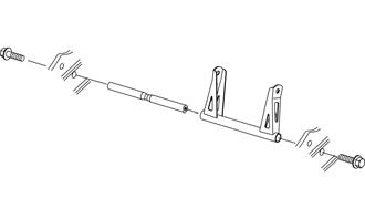
Front Arm Assembly (Slide-Action)
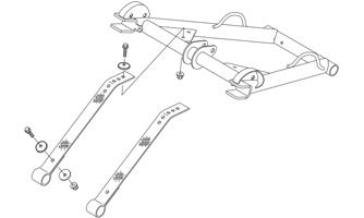
REMOVING 1.With the skid frame removed, remove the cap screws and lock nuts securing the limiter straps to the front arm. Account for flat washers.
SNO-695
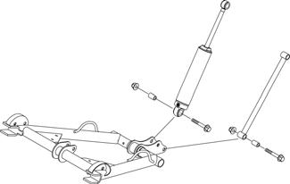
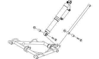
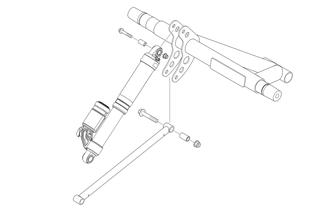
2.Remove the cap screw and lock nut securing the upper front shock absorber eyelet to the front arm.
Pull the shock eyelet free of the bracket. Account for a sleeve.

SNO-696
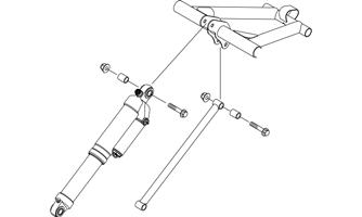
3.Remove the lock nuts and cap screws securing the rear shock pivot and rear shock to the front arm.

SNO-697
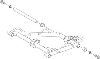
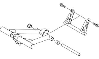
4.Remove the cap screws securing the front arm to the rails.
SNO-698
5.Remove the front arm and account for the front arm axle.
INSPECTING 1.Inspect all front arm weldments for cracks or unusual bends; then inspect the front arm mounting brackets for cracks and for elongated holes. 2.Closely inspect all tubing for cracks or unusual bends.
3.Inspect the bearings, bushings, and front arm spacers for wear or damage. 4.Inspect the shock absorber for damage and for any signs of oil leakage especially at the point where the shock shaft enters the shock body. 5.Inspect the shock absorber eyelet welds (at each end) for any cracks, signs of separation, or for unthreading.
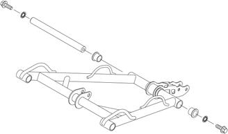
INSTALLING 1.Install the axle into the front arm; then position the front arm with the mounting locations in the slide rails. Secure with the cap screws (threads coated with blue Loctite #243), and a new lock washers.
Tighten to 52 ft-lb.
SNO-698
2.Move the rear arm assembly forward enough to allow the rear arm springs to be installed into the slide blocks.
3.Install the sleeves into the rear shock and the shock link; then secure the shock and link using the existing cap screws and nuts. Tighten to 20 ft-lb.
SNO-697
4.Secure the upper shock eyelet and axle in the mounting hole of the front arm. Secure with a cap screw and lock nut. Tighten to 40 ft-lb.
SNO-696
5.Secure the limiter straps to the front arm with cap screws, washers, and lock nuts. Tighten to 72 in.-lb.
SNO-695
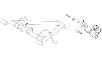
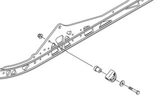
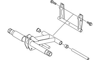
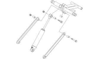
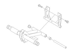
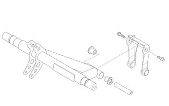
Front Arm Assembly (Pantera/Norseman)
REMOVING 1.With the skid frame removed, remove the cap screws and lock nuts securing the limiter straps to the front arm. Account for flat washers.
SNO-959
2.Remove the cap screw and lock nut securing the upper front shock absorber eyelet to the front arm.
Pull the shock eyelet free of the bracket. Account for a spacers. 3.Remove the two cap screws securing the front arm to the rails. Account for two washers.
SNO-960
INSPECTING 1.Inspect all front arm weldments for cracks or unusual bends; then inspect the front arm mounting brackets for cracks and for elongated holes. 2.Closely inspect all tubing for cracks or unusual bends.
3.Inspect the bearings, bushings, and front arm spacers for wear or damage.
INSTALLING 1.Install the existing axle into the front arm; then position the front arm between the two slide rails and secure using existing cap screws (A) and washers (threads coated with blue Loctite #243). Tighten to 52 ft-lb.
SNO-960
2.Install the spacer into the shock eyelet; then secure the front shock absorber to the front arm using existing cap screw and nut. Tighten to 20 ft-lb. 3.Secure the limiter straps to the front arm using existing cap screws, washers and nuts. Tighten to 72 in.-lb.
SNO-959
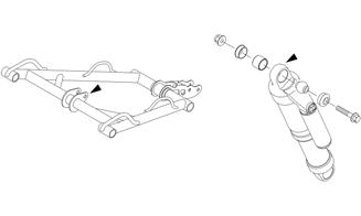
Front Arm Assembly (Float-Action M)
REMOVING 1.With the skid frame removed, remove the cap screws and lock nuts securing the limiter straps to the front arm. Account for flat washers.
SNO-699
2.Remove the cap screw and lock nut securing the upper front shock absorber eyelet to the front arm.
Pull the shock eyelet free of the bracket. Account for a sleeve.

SNO-700
3.Remove the lock nuts and cap screws securing the rear shock pivot and rear shock from the front arm.
SNO-701
4.Remove the cap screws securing the front arm to the rails.
SNO-702
5.Remove the front arm and account for the front arm axle.
INSPECTING 1.Inspect all front arm weldments for cracks or unusual bends; then inspect the front arm mounting brackets for cracks and for elongated holes. 2.Closely inspect all tubing for cracks or unusual bends.
3.Inspect the bearings, bushings, and front arm spacers for wear or damage. 4.Inspect the shock absorber for damage and for any signs of oil leakage especially at the point where the shock shaft enters the shock body.
5.Inspect the shock absorber eyelet welds (at each end) for any cracks, signs of separation, or for unthreading.
INSTALLING 1.Install the axle into the front arm; then position the front arm with the mounting locations in the slide rails. Secure with the cap screws (threads coated with blue Loctite #243), and a new lock washers.
Tighten to 52 ft-lb.

SNO-702
2.Move the rear arm assembly forward enough to allow the rear arm springs to be installed into the slide blocks.
3.Install the sleeves into the rear shock and the shock link; then secure the shock and link using the existing cap screws and nuts. Tighten to 20 ft-lb.
SNO-701
4.Secure the upper shock eyelet and axle in the mounting hole of the front arm. Secure with a cap screw and lock nut. Tighten to 40 ft-lb.
SNO-699
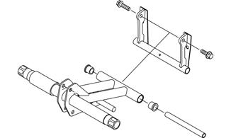
Front Arm Assembly (Alpha One)
CAUTION
Whenever hardware with “Patch-Lock” is removed for service, always replace with new hardware and use only hand tools, not power tools, to tighten the hardware to the proper torque. Failure to follow this will result in improper torque causing damage to the skid frame.
REMOVING 1.With the skid frame removed, remove the cap screws, washers, and the lock nut securing the limiter straps to the front arm and the rail.
0752-765
2.Remove the cap screw and lock nut securing the upper front shock absorber eyelet to the front arm.
Pull the shock eyelet free of the bracket. Account for a sleeve.
SNO-700
0752-766
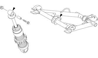
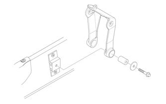
3.Remove the cap screws and lock nuts securing the rear shock pivot and rear shock from the front arm; then remove the cap screws and washers securing the front arm to the rail.
0752-769
4.Remove the front arm and account for the front arm axle.
INSPECTING 1.Inspect all front arm weldments for cracks or unusual bends; then inspect the front arm mounting brackets for cracks and for elongated holes. 2.Closely inspect all tubing for cracks or unusual bends.
3.Inspect the bearings and bushings for wear or damage. 4.Inspect the shock absorber for damage and for any signs of oil leakage especially at the point where the shock shaft enters the shock body.
INSTALLING 1.Install the axle into the front arm; then position the front arm with the mounting locations in the rail.
Secure with new cap screws, spacer, and washers.
Tighten to 52 ft-lb.
0752-769
2.Install the axle into the rear shock and the rear shock link; then secure the shock and rod to the shock pivot using the existing hardware. Tighten to 24 ft-lb. 3.Secure the upper shock eyelet and axle in the mounting hole of the front arm. Secure with a cap screw and lock nut. Tighten to 24 ft-lb.
0752-766
4.Secure the limiter strap around the front arm and secure to the rail using the existing cap screws, washers, and lock nut. Tighten the upper cap screw and nut to 72 in.-lb and the bottom cap screw and washer to 15 ft-lb.
0752-765
Rear Arm Assembly (Slide-Action)
REMOVING 1.With the skid frame removed using the Rear Suspension Spring Tool, remove the spring from the adjusting cam.
2.Mark the offset arm and the idler arm for assembly purposes. 3.Loosen the cap screw and lock nut securing the offset arm assembly to the idler arm; then remove the offset arm assembly. Account for a flanged axle, idler spacer, and washer.
! WARNING
Care must be taken when removing the spring or damage or injury could result.
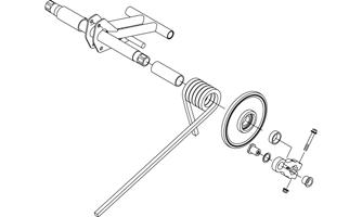
SNO-709
4.Remove the idler wheel using the Idler Wheel Puller
Kit.
5. Remove the cap screw, flat washer, and lock nut securing the spring slide to the slide rail. Account for the spring slide and the slide block.
SNO-710
6.Remove the spring and sleeve from the idler arm.
Repeat for opposite side. 7.Remove the cap screw and lock nut securing the upper shock eyelet to the idler arm; then remove the cap screw and lock nut securing the upper shock link to the idler arm. Account for the cap screws, lock nuts, and sleeves.
SNO-711
8.Remove the cap screws securing the rear arm to the idler arm. Account for the aluminum axle.
SNO-712
9.Remove the cap screw and lock nut securing the rear arm to the slide rail. Account for the serrated axles and axle tube.
SNO-713
CLEANING AND INSPECTING 1.Clean the bearings with a clean cloth. 2.Inspect each idler wheel for cracks or damage. 3.Inspect the bushings (located in the arm pivot area) for wear or damage. 4.Inspect all welds and the tubing of the rear arm/idler arm for cracks or unusual bends.
5.Inspect the two adjusting cams for damage. 6.Rotate the idler wheel bearings (by hand) and check for binding or roughness.
7.If a bearing must be replaced, see Idler
Wheels/Mounting Blocks - Cleaning and Inspecting in this sub-section.
INSTALLING 1.Place the rear arm assembly into position between the slide rails. Secure with the existing cap screws (threads coated with blue Loctite #243). Tighten to 40 ft-lb.
SNO-713
2.Install the rear arm onto the idler arm with an aluminum axle and two cap screws. Tighten to 40 ft-lb.
SNO-712
3.With the sleeves installed, install the shock absorber link to the lower mounting hole of the idler arm along with the cap screw and lock nut; then secure the shock absorber to the idler arm with cap screws and lock nuts. Tighten to 20 ft-lb.
SNO-711
NOTE: Do not over-tighten the shock absorber cap
screw as the shock eyelet must be free to pivot.
NOTE: Install the rear arm springs onto the
adjuster blocks after the skid frame has been installed.
4.Slide the sleeve and spring onto the idler arm. 5.Place the spring slide and slide block (with spring in slide block) into position on the slide rail. Secure with a cap screw and washer. Tighten to 20 ft-lb. 6.With wheel insertion tool, install the rear upper idler wheel on the idler arm.
7.Install the idler spacer collar onto the idler arm; then place the flared bushing with a thin flat washer through the notched side of the offset arm assembly. 8.Place the flared bushing with a thin flat washer through the notched side of the offset arm assembly.
CAUTION
When driving the idler wheel onto the idler arm, use a tool to contact the inside race of the bearing or damage to the wheel or bearing may occur.
NOTE: If the flared bushing in the offset arm is
loose, it must be cleaned and green Loctite #609 must be applied to it prior to installation.
9.Align the marks on the idler arm to the centerline of the offset arm assembly. Secure the offset arm to the idler arm with the existing cap screw and lock nut.
Tighten to 20 ft-lb.
SNO-709
10.Grease the idler arm and rear arm grease fittings with low-temperature grease.
Rear Arm Assembly (Pantera/Norseman models)
REMOVING 1.Remove the skid frame; then remove the slide spring from the adjusting cam.
! WARNING
Care must be taken when removing the spring or damage or injury could result.
2.Mark the offset arm and the idler arm for assembly purposes. 3.Remove the idler wheel.
NOTE: Use the Idler Wheel Puller Kit to remove
the wheel.
4. Remove the cap screw, flat washer, and lock nut securing the spring slide to the slide rail. Account for the spring slide and all mounting hardware.
5.Remove the spring and sleeve from the idler arm. NOTE: Use the same procedure for the other side. 6.Remove the cap screw and lock nut securing the upper shock eyelet to the idler arm; then remove the cap screw and lock nut securing the upper shock link to the idler arm. Account for the cap screws, lock nuts, and sleeves.
SNO-962
7.Remove the cap screw securing the rear arm to the idler arm. Account for the aluminum axle.
SNO-961
8.Remove the cap screw and lock nut securing the rear arm to the slide rail. Account for the serrated axles and axle tube.
CLEANING AND INSPECTING 1.Clean the bearings with a clean cloth. 2.Inspect each idler wheel for cracks or damage. 3.Inspect the bushings (located in the arm pivot area) for wear or damage. 4.Inspect all welds and the tubing of the rear arm/idler arm for cracks or unusual bends. 6.Rotate the idler wheel bearings (by hand) and check for binding or roughness. 7.If a bearing must be replaced, see Idler
Wheels/Mounting Blocks — Cleaning and Inspecting in this sub-section.
INSTALLING 1.Place the rear arm assembly into position between the slide rails. Secure with a cap screw and lock nut.
Tighten to 40 ft-lb. 2.Install the rear arm onto the idler arm with an aluminum axle and two cap screws. Tighten to 40 ft-lb.
SNO-961
3.With the sleeves installed, install the shock absorber link to the lower mounting hole of the idler arm along with the cap screw and lock nut; then secure the shock absorber to the idler arm with cap screws and lock nuts. Tighten to 40 ft-lb.
SNO-962
NOTE: Do not over-tighten the shock absorber cap
screw as the shock eyelet must be free to pivot.
NOTE: Install the rear arm springs onto the
adjuster cams after the skid frame has been installed.
4.Slide the sleeves and springs onto the idler arm. 5.Place the spring slide and slide block (with spring in slide block) into position on the slide rail. Secure with a cap screw and washer. Tighten to 20 ft-lb.
7.Install the idler spacer collar onto the idler arm. 8.Place the flared bushing with a thin flat washer through the notched side of the offset arm assembly.
CAUTION
When driving the idler wheel onto the idler arm, use a tool to contact the inside race of the bearing or damage to the wheel or bearing may occur.
NOTE: If the flared bushing in the offset arm is
loose, it must be cleaned and green Loctite #609 must be applied to it prior to installation.
9.Align the marks on the idler arm to the centerline of the offset arm assembly. Secure the offset arm to the idler arm with cap screws and lock nuts. Tighten to 20 ft-lb.
NOTE: When tightening the offset arm lock nuts,
tighten the upper lock nut first to ensure an even clamp load. Make sure the flared side of the bushing is directed outward.
10.Grease the idler arm and rear arm grease fittings with low-temperature grease.
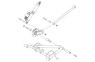
Rear Arm Assembly (Float-Action)
DISASSEMBLING 1.With the skid frame removed, remove the snap ring securing the rear arm idler wheels to the inner carriage axle and account for the wave washers; then remove the axle from the idler arm.

SNO-704
2.Remove the cap screw and lock nut securing the upper shock eyelet to the idler arm; then remove the cap screw and lock nut securing the rear shock link to the idler arms.

SNO-705
3.Remove the cap screws and lock nuts securing the rear arm shock absorber and shock link to the offset arm.
SNO-701
NOTE: With the rear arm shock and shock link
removed, account for the four sleeves.
4.Remove the cap screw and lock nut securing the rear arm to the idler arm. Account for the aluminum axle and flared bushings.

SNO-706
NOTE: To loosen and remove the remaining cap
screw from the rear arm/idler arm, it may be necessary to reinstall the cap screw.
5.Remove the cap screw and lock nut securing the rear arm to the slide rail. Account for the bushings and axle tube.

SNO-707
CLEANING AND INSPECTING 1.Clean the bearings with a clean cloth. 2.Inspect each idler wheel for cracks or damage. 3.Inspect the bushings (located in the arm pivot area) for wear or damage. 4.Inspect all welds and the tubing of the upper arm for cracks or unusual bends.
5.Inspect the two adjusting cams for damage. 6.Rotate the idler wheel bearings (by hand) and check for binding or roughness. 7.If a bearing must be replaced, see Idler
Wheels/Mounting Blocks — Cleaning and Inspecting.
ASSEMBLING 1.Place the rear arm assembly into position between the slide rails. Secure with existing cap screws (threads coated with blue Loctite #243). Tighten to 20 ft-lb.
SNO-707
2.Install the idler arm onto the rear arm with an aluminum axle, bushing assemblies, and two cap screws (threads coated with blue Loctite #243). Tighten to 40 ft-lb.
SNO-706
3.With the sleeves installed, place the shock absorber and shock link between the offset arm bracket.
Secure with the cap screws and lock nuts. Tighten securely.
SNO-701
NOTE: Do not over-tighten the shock absorber cap
screw as the shock eyelet must be free to pivot.
4.With the sleeves installed, position the shock link in the appropriate holes of the idler arm brackets and shock absorber; then insert the cap screw through the eyelets. Secure with the cap screws and lock nuts.
Tighten securely.
SNO-705
5.Install the inner carriage axle to the idler arm; then install a wave washer and idler wheel. Secure with the snap ring. 6.Turn the slide rail onto the side the idler wheel was installed in (from step 5); then with a block of wood placed under the inner carriage axle/idler arm, install a wave washer.
SNO-704
7.Install the remaining idler wheel along with the snap ring onto the axle; then using a suitable driving tool, carefully drive the snap ring into the idler wheel until properly seated in the groove of the axle. 8.Grease the idler arm and rear arm grease fittings with low-temperature grease.
Rear Arm Assembly (Alpha One)
CAUTION
Whenever hardware with “Patch-Lock” is removed for service, always replace with new hardware and use only hand tools, not power tools, to tighten the hardware to the proper torque. Failure to follow this will result in improper torque causing damage to the skid frame.
DISASSEMBLING 1.With the skid frame removed, remove the snap ring securing the rear arm idler wheels to the inner carriage axle and account for the wave washers; then remove the axle from the idler arm.
0752-772
3.Remove and discard the cap screws securing the rear arm to the idler arm. Account for the aluminum axle and flared bushings.
0752-773
NOTE: To loosen and remove the remaining cap
screw from the rear arm/idler arm, it may be necessary to reinstall the cap screw.
4.Remove and discard the cap screws and washers securing the rear arm to the rail. Account for the bushings.
0752-771
2.Remove the cap screw and lock nut securing the upper shock eyelet to the idler arm; then remove the cap screw and lock nut securing the rear shock link to the idler arm.
0752-774
CLEANING AND INSPECTING 1.Clean the bearings with a clean cloth. 2.Inspect each idler wheel for cracks or damage. 3.Inspect the bushings for wear or damage. 4.Inspect all welds and the tubing of the upper arm for cracks or unusual bends.
ASSEMBLING 1.Place the rear arm assembly into position onto the rail. Secure with new cap screws, axles, and washers.
Tighten to 13 ft-lb.
0752-744
2.Install the idler arm onto the rear arm with an aluminum axle, bushing assemblies, and two new cap screws. Tighten to 24 ft-lb.
0752-773
3.With the sleeves installed, position the shock link and the shock in the appropriate holes of the idler arm; then insert the cap screw through the eyelets.
Secure with the cap screws and lock nuts. Tighten to 24 ft-lb.
0752-772
4.Install the inner carriage axle to the idler arm; then install a wave washer and idler wheel. Secure with the snap ring. 5.Turn the skid frame onto the side the idler wheel was installed in; then, with a block of wood placed under the inner carriage axle/idler arm, install a wave washer.
0752-771
6.Install the remaining idler wheel along with the snap ring onto the axle; then using a suitable driving tool, carefully drive the snap ring into the idler wheel until properly seated in the groove of the axle. 7.Grease the idler arm and rear arm grease fittings with low-temperature grease.
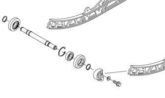
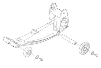
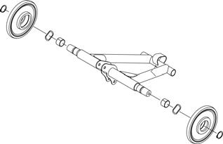
Rear Axle/Idler Wheels (ZR/XF/Pantera)
DISASSEMBLING REAR AXLE 1.Remove both cap screws and washers securing rear wheel assembly to the rails. 2.Loosen the track adjusting bolts; then carefully remove the rear axle assembly from the skid frame.
Account for a spacer, an idler wheel, adjuster bushings, and a washer between the rails.
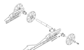
ONS-111
ASSEMBLING REAR AXLE 1.Install the adjuster bushing, inner idler wheel, spacer, axle, and washer between the rails. 2.Place the outer adjuster bushings on the axle; then install the idler wheels and secure with two cap screws (coated with blue Loctite #243) and flat washers. Tighten cap screws only until snug.
ONS-111
NOTE: Tighten the rear idler wheel axle only until
snug until the skid frame has been installed and track tension has been adjusted; then the axle assembly must be tightened to 35 ft-lb.
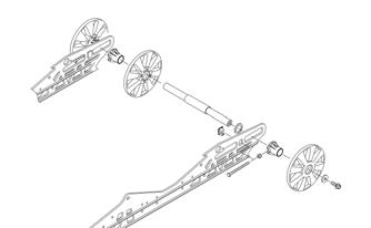
Rear Axle/Idler Wheels (Norseman models)
DISASSEMBLING REAR AXLE 1.Remove the idler wheel caps from the outer wheels; then remove both cap screws and washers securing rear wheel assembly to the rails.
ONS-050
2.Loosen the track adjusting bolts; then carefully remove the rear axle assembly from the skid frame.
Account for spacers, an idler wheel, and two washers between the rails.
ASSEMBLING REAR AXLE 1.Install the adjuster bushing, inner idler wheel, spacers, axle, and washers between the rails. 2.Place the outer adjuster bushings on the axle; then install the idler wheels and secure with two cap screws (coated with blue Loctite #243) and flat washers. Tighten cap screws only until snug.
ONS-050
NOTE: Tighten the rear idler wheel axle only until
snug until the skid frame has been installed and track tension has been adjusted; then the axle assembly must be tightened to 35 ft-lb.
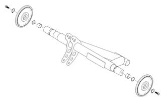
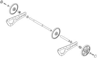
Rear Axle/Idler Wheels (XF HC/M)
DISASSEMBLING REAR AXLE 1.Remove both cap screws and washers and securing rear wheel assembly to the rails.
ONS-105
2.Loosen the track adjusting bolts then carefully remove the rear axle assembly from the skid frame.
ASSEMBLING REAR AXLE 1.If the rear idler wheels were separated, install both wheels onto the axle and secure using the existing cap screws and nuts. Tighten to 80 in.-lb. 2.Place the adjuster bushings on the axle; then install the idler wheels and secure with two cap screws (coated with blue Loctite #243) and flat washers.
Tighten cap screws only until snug.
ONS-105
NOTE: Tighten the rear idler wheel axle only until
snug until the skid frame has been installed and track tension has been adjusted; then the axle assembly must be tightened to 35 ft-lb.
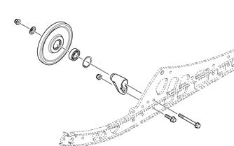
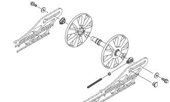
Rear Axle/Idler Wheels (Alpha One)
DISASSEMBLING REAR AXLE 1.Remove the cap screw, washers, and nut securing rear wheel assembly to the rail. 2.Remove the wheels, sleeves, and the track tension shaft from the rail.
ONS-114
ASSEMBLING REAR AXLE 1.Position the track tension shaft into the rear slot in the rail; then install the sleeves over the shaft. 2.Position the wheels with the sleeves and secure using the existing cap screw, washers, and nut.
ONS-114
NOTE: Tighten the rear idler wheel axle only until
snug until the skid frame has been installed and track tension has been adjusted; then the rear cap screw should be tightened to 24 ft-lb.
Installing Skid Frame (Slide-Action Models)
1.Using a piece of cardboard on the floor to protect against scratching and an appropriate handlebar/steering post stand, tip the snowmobile onto one side.
2.Pull the track away from the tunnel and spread open; then place the skid frame into the track. 3.Position the front of the skid frame into the tunnel and engage the front arm with the slider axle in the tunnel.
0742-187
4.Push the rear of the skid frame and the track into the tunnel.
5.Align the rear arm assembly with the appropriate hole in the tunnel. Secure the rear arm assembly with the cap screw (coated with blue Loctite #243). 6.Tip the snowmobile onto the other side; then align the offset arm assembly with the appropriate hole in the tunnel. Secure the rear arm assembly with the cap screw (coated with blue Loctite #243). 7.Using the Rear Suspension Spring Tool, install the short legs of the rear springs onto the adjusting cams making sure the cams are in the same adjustment positions.
ZR-258
9.On iACT models, remove the cable tie securing the rear shock harness to the front arm; then route the harness and grommet up through the tunnel. 10.On iACT models, connect the rear shock harness to the suspension module harness; then secure the harness to the tunnel using the existing clamps, screws, and nut. Tighten securely.
ZR-259
11.Adjust track tension and track alignment.
CAUTION
After proper track tension and alignment have been attained, make certain that the rear axle cap screws tightened to specifications or component damage will occur.
Installing Skid Frame (Float-Action Models)
1.Using a piece of cardboard on the floor to protect against scratching and an appropriate handlebar/steering post stand, tip the snowmobile onto one side.
2.Pull the track away from the tunnel and spread open; then place the skid frame into the track. 3.On M models, Secure the front of the skid frame to the tunnel using the existing cap screws, spacers, flat washers, and lock nuts. 4.On Alpha One models, install the hook end of the ice scratcher around the front arm tube; then install the flared bushing through the ice scratcher and aligning with the front mounting location in the arm. Secure using the existing cap screw and bushing.
ONS-115
5.Push the rear of the skid frame and the track into the tunnel.
6.Align the rear arm assembly with the appropriate hole in the tunnel. Loosely secure the rear arm assembly with the cap screw (coated with blue Loctite #243). 7.Tip the snowmobile onto the other side; then align the offset arm assembly with the appropriate hole in the tunnel. Loosely secure the rear arm assembly with the cap screw (coated with blue Loctite #243). 8.Return the snowmobile to the upright position; then tighten all cap screws to 40 ft-lb. 9.Adjust track tension and track alignment.
CAUTION
After proper track tension and alignment have been attained, make certain that the rear axle cap screws tightened to specifications or component damage will occur.
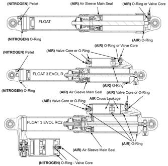
FOX Air Shocks
AIR LEAKAGE POINTS NOTE: When attaching the air pump, the hose and
gauge will fill with air from the air chamber resulting in a lower air pressure reading than the shock was originally set at. This is normal.
1.Check for leaks at room temperature and cold temperatures. Set the shock outside overnight during the winter months.
2.Charge the shock to 100 psi; then fill a 5-gallon pail of water.
3.Remove the air valve cap(s) and submerge the shock in water. Look for air bubbles to determine if a seal or O-ring has failed.
SNO-663
4.If service work is needed on any FOX shocks, the shock will have to be removed and sent to FOX or any FOX distributor for any service work. For FOX shock information, visit www.ridefox.com.
REPLACING AIR VALVE/O-RING 1.If an air leak is detected around the air valve, remove and discard the existing air valve and O-ring. Install new air valve and O-ring. Tighten to 35 in-lb.
SNO-666
Servicing IFP Shock
SPECIAL TOOLS A number of special tools must be available to the technician when servicing the rear suspension.
Description
Piston Location (IFP) Tool Inflation Needle Tool Rear Suspension Spring Tool Shock Body Clamping Tool Shock Rod Clamp Tool Bearing Cap Seal Protector Tool Shock Spring Removal Tool
p/n
0644-575 0744-020 0144-311 0644-486 0644-425 0644-268/403/404 0644-057 NOTE: Special tools are available from the Arctic
Cat Service Parts Department.
NOTE: If service work is needed on any FOX
shocks, the shock will have to be removed and sent to FOX or any FOX distributor for any service work. For FOX shock information, visit www.ridefox.com.
! WARNING
Before any service is performed on the gas shock absorber, first discharge all pressure from the shock remote reservoir. Remove the valve screw from the pressure valve and insert the Inflation Needle. Open valve until all pressure is released. Failure to do this may cause personal injury.
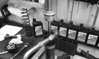
REMOVING/CLEANING 1.Remove the shock from the snowmobile; then remove the spring from the shock body using the shock spring removal tool. 2.Wash the shock body in parts-cleaning solvent.
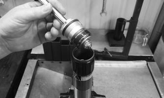
DISASSEMBLING 1.Remove the screw from the bottom of the shock.
Discharge all the pressure from the shock using the
Inflation Needle. Open the valve in filler handle until all pressure is released.
ZR-004
ZR-017
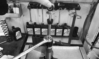
2.Using a 1-in. wrench, loosen the bearing assembly and remove the shock rod and valve assembly from the shock body.
ZR-003
ZR-016
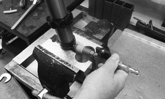
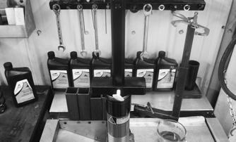
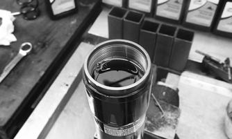
3.Pour the oil from the shock body into a suitable container; then hang the shock body upside down and let it drip into the container. 4.Clamp the shock rod and valve assembly in bench vise; then remove the nut securing the valve stack.

ZR-011
NOTE: Placing the valve stack on a screwdriver
when removing from the shock rod will allow the shims and valve to stay in order.
5.Remove the bearing end cap. 6.Items to inspect:
A.Shock rod for straightness, nicks, or burrs.
B.Bearing end cap — clean, inspect, or replace.
C.Inside of shock body for scratches, burrs, or excessive wear.
D.Piston strap for cuts, chipped or nicked edges, or excessive wear.
G.Rubber damper (ski shocks only) for chipping, cracking, or being missing. 7.Items to replace:
A.Floating piston O-ring.
B.Shock shaft bearing cap if any signs of oil leaks or damage.
C.Any part worn or damaged.
ASSEMBLING 1.Lubricate the O-rings in the bearing end cap; then install the bearing cap seal protector onto the end of the shock rod. Install the bearing end cap.
ZR-013
2.Install the valve stack onto the shock rod; then secure using the existing nut. Tighten to 15 ft-lb.
ZR-014
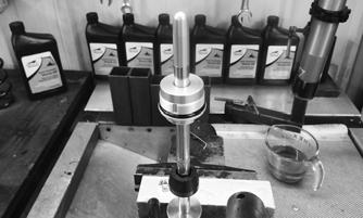
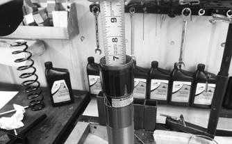
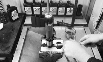
3.Using Piston Location (IFP) Tool or a tape measure, make sure the floating piston is at the correct depth in the shock body (according to the chart in the specifications section of the manual).
ZR-009
4.If the floating piston is not at the correct depth, use the floating piston location gauge to set the piston to the correct depth in the shock body.
ZR-008
5.Fill shock body with new synthetic shock oil to bottom of threads.
ZR-007
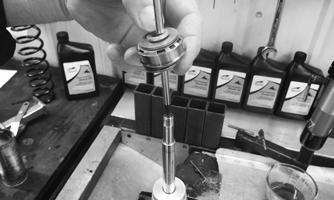
6.With the bearing cap positioned at the top of the shock rod, install the piston/valve stack into the shock body; then gently tap the top of the rod eyelet with a soft hammer until the piston/valve stack is just below the oil.
NOTE: Using a torch, carefully wave the flame over
the top of the shock oil to remove any air bubbles.
ZR-006
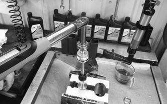
7.Slide the bearing cap down to the shock body and into the oil; then while holding the shock rod in place, begin to thread the cap into the body. As the cap threads into the body, oil will escape. Lift slightly on the shaft while threading until the O-ring contacts the shock body. Tighten the bearing cap to 50 ft-lb.
ZR-003
8.With shock oil around the seals in the bearing cap and on the shock rod, slowly compress the shock rod until the shock eyelet bottoms out. Pressurize the shock with nitrogen to 200 psi and until the shock eyelet fully extends.
ZR-018
9.Install the screw into the shock body.
INSTALLING 1.Place the shock into position on the snowmobile. 2.Secure with existing hardware and bushings.
ZR-004
10.Compress the shock eyelet until it bottoms out; then the shock eyelet should fully extended. Wash the shock and install the spring.