4. An injector coil located on the stator provides the injectors with DC voltage for operation through the ECM.
Fuel Systems This section has been organized for servicing the fuel systems; however, some components may vary from model to model. The technician should use discretion and sound judgment when removing/disassembling and assembling/installing components. Whenever any maintenance or inspection is made on the fuel system where fuel leakage may occur, there should be no welding, smoking, or open flames in the area.
5. A lighting coil located on the stator plate provides output to the regulator/rectifier (8000) to operate accessories and the lighting system. FLOODED ENGINE
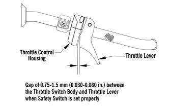
If the engine should become flooded, set the brake lever lock, compress the throttle lever to the full-open position, and crank the engine over until it starts and clears itself. Release the brake lever lock. FUEL SYSTEM
NOTE: Whenever a part is worn excessively, cracked, or damaged in any way, replacement is necessary.
The fuel is first drawn into the electric fuel pump through multiple pick-up valves and hoses. The fuel is then routed through a high-pressure fuel hose to the fuel rail.
SPECIAL TOOLS
The fuel pressure is maintained in the fuel rail by the fuel regulator. With the fuel pressure maintained at a constant psi, the ECM evaluates the information it receives from the electrical sensors and opens the injectors for precise periods of time (pulse widths) to meet engine demands.
A number of special tools must be available to the technician when servicing the fuel systems. Description
p/n
CATT II
0554-023
EFI Analyzer
0744-049
EFI Diagnostic System Manual
2257-850
EFI Diagnostic System Manual (Instructions)
2259-020
Fluke Model 77 Multimeter
0644-559
Fuel Hose Clamp Tool
0644-545
NOTE: The entire EFI system depends on all coils functioning properly on the stator.
Individual Components
EFI Fuel Pressure Test Kit
0644-587
Vacuum Test Pump
0644-131
ECM
Fuel Pump Installation Tool Kit
0744-074
Laptop Diagnostic Test Kit
0744-050
The ECM is the brain of the EFI system. It uses sensor inputs to determine the correct fuel/air ratio for the engine given the existing conditions of altitude and temperature.
Laptop Diagnostic Tool
0744-060
Oil Injection Usage Tool
0644-007
NOTE: Special tools are available from the Arctic Cat Service Parts Department.
EFI System INTRODUCTION
The Arctic Cat EFI System operates off a series of coils located on the stator and is made up of the following components: 1. An engine control module (ECM) calculates input from sensors (exhaust temperature sensor, air temperature sensor, coolant temperature sensor, throttle position sensor, ignition timing sensor, barometric pressure sensor, and a knock sensor) to provide the engine with the correct fuel mixture and timing for optimum operation. 2. Charge coils (1 and 2), located on the stator, provide AC voltage to the ECM/regulator/rectifier where AC voltage is converted to DC voltage. 3. A fuel pump coil located on the stator operates the low voltage, high output fuel pump. At cranking speed, the high output fuel pump provides enough fuel to charge the fuel rail.
If any of the sensors should fail while the engine is running, the ECM will sense a problem and go into a “fail safe” mode. This is an over-rich condition and will greatly reduce performance. However, the engine will be protected from a possible lean condition and engine damage. The ECM is equipped with a self-diagnostic system utilizing the service icon in the speedometer/tachometer and remains illuminated when a problem exists with any of the sensors. The technician can determine the problem sensor by reading the code shown on the readout screen and applying it to the ECM Diagnostic Codes chart (see Self-Diagnostic System/Codes in this section). NOTE: The ECM cannot be repaired.
If the ECM is not receiving current from one of the output coils on the stator, that circuit will not operate. Coils on the stator are the charge coils operating the ECM, the injector coil which operates the injectors, the fuel pump coil which operates the fuel pump, and the lighting coil/chassis control unit operating all accessories and the lighting system. Removing
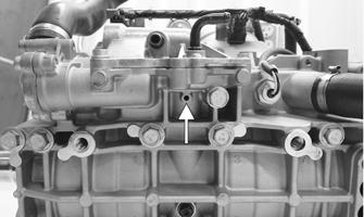
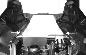
1. Remove the expansion chamber. 2. Remove the two Torx-head screws securing the rear portion of the ECM heat shield; then remove the shield. 85