REMOVING
Drive Train/Track/Brake Systems This section has been organized into sub-sections for servicing drive train, track, and brake systems; however, some components may vary from model to model. The technician should use discretion and sound judgment when removing and installing components.
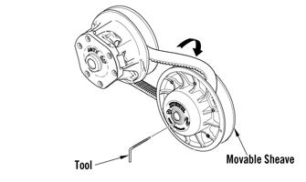
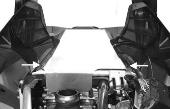
1. Set the brake lever lock; then remove the left-side access panel. Loosen the 1/4 turn on the lower console. 2. Using Drive Belt Deflection Tool, thread the tool clockwise into the driven clutch until the movable sheave opens far enough to remove the drive belt.
NOTE: Whenever a part is worn excessively, cracked, or damaged in any way, replacement is necessary. SPECIAL TOOLS
A number of special tools must be available to the technician when servicing the drive train, track, and brake systems. Description
p/n
Drive Clutch Bolt Tool
0644-281
Drive Belt Deflection Tool
0644-424
Bearing Removal and Installation Tool
0644-167
Brake Disc Socket
0644-481
Movable Sheave Bearing Tool
0644-594
Clutch Alignment Bar
0744-097
Drive Clutch Puller
0744-062
Drive Clutch Spanner Wrench
0644-136
Driven Clutch Compressor Tool
0644-444
Rear Suspension Spring Tool
0144-311
Brake Caliper Bearing Puller
0744-067
NOTE: Special tools are available from the Arctic Cat Service Parts Department.
743-067B
INSTALLING
1. Place the belt (so the part number can be read) between the sheaves of the drive clutch. 2. With the sheaves fully apart, roll the belt over the stationary sheave. 3. With the drive belt properly positioned in the drive clutch and driven clutch, turn the belt tool counterclockwise, release the brake lever lock, and roll the belt back and forth to allow the driven clutch sheaves to fully close. 4. After the belt is installed properly, secure the access panel.
CAUTION Never attempt to substitute any other drive clutch puller for the recommended puller or severe clutch damage will occur.
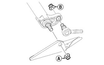
Drive Clutch CHANGING CAM ARMS/SPRING
Drive Belt If the drive belt is longer than specified, the drive clutch and driven clutch will not achieve full shift ratio. This will result in poor acceleration and a decrease in top speed. If the drive belt is shorter than specified, the starting ratio will be higher causing the belt to slip. A too-short drive belt will cause a bog on engagement and will not allow the engine to reach peak RPM. NOTE: A thinly-worn drive belt may produce the same effect as one that is too long. NOTE: A stiff belt causes a HP loss to the track. As a belt warms up, it gets more flexible and transmits power with less HP loss. NOTE: When installing a new drive belt, see After
Break-In Checkup — Drive Belt Break-In in the General Information section.
Removing
1. Using Drive Clutch Bolt Tool, remove the Torx-head screw and lock washer securing the drive clutch to the crankshaft. NOTE: Before installing the clutch puller, apply oil to the threads of the puller and a small amount of grease to the tip of the puller.
2. Using the Drive Clutch Puller and the Drive Clutch Spanner Wrench, tighten the puller. If the drive clutch will not release, sharply strike the head of the puller. Repeat this step until the clutch releases. 3. Remove the drive clutch from the engine compartment. Disassembling NOTE: Note the timing marks on the cover, spider, and movable sheave. These must be aligned when assembling the drive clutch for balance purposes.
103