3 minute read
3.2 Removing and installing air filter housing


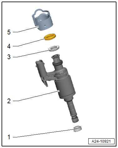
– Before installing injector -2- moisten new O-ring -4- with clean engine oil.
Note
The combustion chamber seal -1- must not be lubricated.
• Electrical connector of injector must engage in respective re‐cess in cylinder head. • The injector should enter smoothly. Where necessary, wait until the combustion chamber seal has contracted sufficiently. – Push injector by hand as far as it will go into the hole of the cylinder head (which must be free of oil and grease). Ensure injectors are positioned correctly in cylinder head. – Installing fuel rail ⇒ “2.2 Removing and installing fuel rail”, page 385 . – Then replace the injection valves which have to be adapted again. – Connect a ⇒ Vehicle diagnostic tester. – Switch on ignition, select and execute following menu options on ⇒ Vehicle diagnostic tester:
♦ 0001 - Delete adaption values of the injection valves
2.4 Cleaning injectors
Special tools and workshop equipment required ♦ Ultrasonic cleaning device - VAS 6418-
Protected by copyright. Copying for private or commercial purposes, in part or in whole, is not permitted unless authorised by SEAT S.A. SEAT S.A does not guarantee or accept any liability with respect to the correctness of information in this document. Copyright by SEAT S.A.

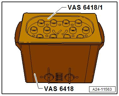
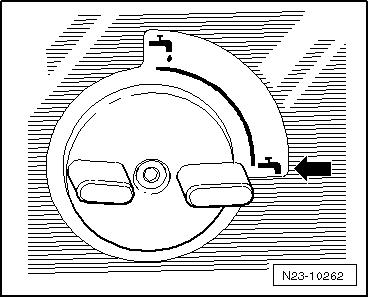
♦ Mounting plate for injection modules - VAS 6418/1♦ Cleaning agents: ⇒ Electronic parts catalogue Cleaning – Close drain tap -arrow- of ultrasonic cleaning unit - VAS 6418at right-hand side of housing. – Fill ultrasonic cleaning unit with 2120 ml of water which was allowed to stand for a while and with cleaning fluid - VAS 6418/2- .
Mixing ratio for cleaning fluid • 2100 ml of water which was allowed to stand for a while and 20 ml of cleaning fluid - VAS 6418/2- . – Remove injectors ⇒ page 386 .
– Fit mounting plate for injection modules - VAS 6418/1- onto cleaning unit.
Note
♦ Before starting ultrasonic cleaning unit - VAS 6418- , it is es‐sential that the safety information described in the operating manual is observed.
♦ The ideal fluid level is reached when the cleaning agent is ap‐prox. 1 to 4 mm above the base of the support plate. The ultrasonic cleaner - VAS 6418- could become damaged if the fluid level is too low.
– Insert injectors into guides of mounting plate for injection mod‐ules - VAS 6418/1- as far as stop.
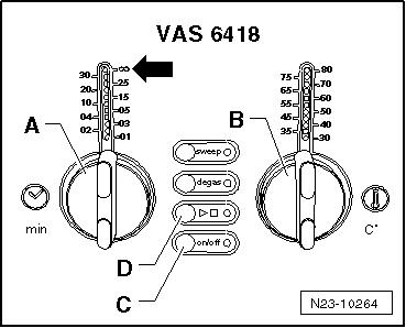
– Switch on cleaning unit by pressing on/off button -C-.
– Use rotary knob -A- to set cleaning time to 30 minutes. – Set rotary knob -B- to a temperature of 50°C. – Press button ► -D- to start the cleaning process.
Note
♦ Temperature-controlled cleaning is now activated. During the
Protected by copyright. Copying for private or commercial purposes, in part or in whole, is notwarm-up period, ultrasonic waves are activated to mix the permitted unless authorised by SEAT S.A. SEAT S.A does not guarantee or accept any liability with respect to the correctness of information in this document. Copyright by SEAT S.A.cleaning fluid. Once the preselected temperature is reached, the ultrasonic waves are switched to continuous operation. ♦ The cleaning time must be at least 30 minutes and cleaning only starts at a temperature of at least 50°C.
– Each time after cleaning injectors (combustion chamber), re‐new combustion chamber seal (Teflon ring seal) ⇒ “2.3 Removing and installing injectors”, page 386 .


