4 minute read
1.2 Removing and installing turbocharger


– Connect the electrical connector -2-.
– Clip in wiring harness -arrows-.
– Fit seal -2- to frame of radiator blind -1-.
– Make sure it is properly positioned on recesses -3- and -4-. – Clip in seal -2-. – After replacing radiator blind control motor - V544- , a basic setting must be performed. – Use ⇒ Vehicle diagnostic tester. – Clear event memory ⇒ Vehicle diagnostic tester. – Switch on ignition, select and execute following menu options on ⇒ Vehicle diagnostic tester:
♦ 0001 - Radiator blind control motor adaption -
V544
4.9 Assembly overview - radiator blind
⇒ “4.9.1 Assembly overview - radiator blind”, page 347 ⇒ “4.9.2 Assembly overview - components of radiator blind”, page 349
4.9.1 Assembly overview - radiator blind
Protected by copyright. Copying for private or commercial purposes, in part or in whole, is not permitted unless authorised by SEAT S.A. SEAT S.A does not guarantee or accept any liability with respect to the correctness of information in this document. Copyright by SEAT S.A.

1 - Bumper carrier ❑ Assembly overview ⇒ General body repairs, exterior; Rep. gr. 50 ; Lock carrier; Assembly overview - lock carrier
2 - Rear seal
3 - Radiator blind control motor - V544❑ Removing and installing 4 - Locking lugs ❑ For seals
5 - Ambient temperature sen‐sor - G17❑ Fitting location ⇒ Item 12 (page 348) ❑ Clipped into front seal ❑ ⇒ Current flow dia‐grams, Electrical fault finding and Fitting loca‐tions
6 - Radiator blind ❑ Removing and installing 7 - Connector contact ❑ For radiator blind control motor - V544❑ Secured to lock carrier. ❑ ⇒ Current flow dia‐grams, Electrical fault finding and Fitting loca‐tions
8 - Support ❑ For securing connector contact to lock carrier ⇒ Item 7 (page 348) 9 - Bolt ❑ 2 off ❑ 8 Nm
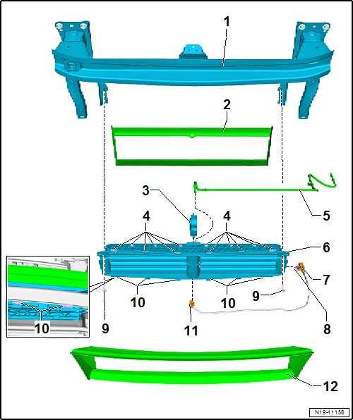
10 - Wiring harness ❑ For radiator blind control motor - V544❑ ⇒ Current flow diagrams, Electrical fault finding and Fitting locations 11 - Locking lugs ❑ For seals
12 - Front seal
Protected by copyright. Copying for private or commercial purposes, in part or in whole, is not permitted unless authorised by SEAT S.A. SEAT S.A does not guarantee or accept any liability with respect to the correctness of information in this document. Copyright by SEAT S.A.
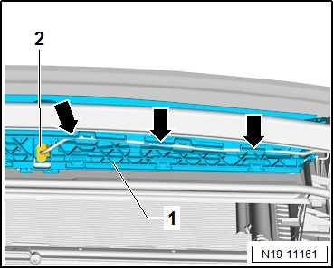
Routing cables/lines on radiator blind – Wiring harness -2- for radiator blind control motor - V544- is clipped into frame of radiator blind -1- -arrows-.
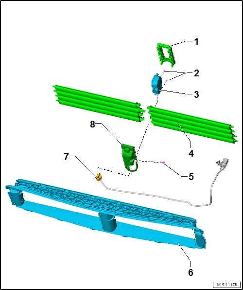
1 - Connecting link 2 - Bolt ❑ 1.5 Nm
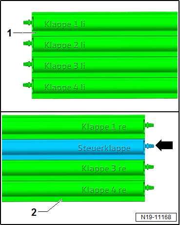
3 - Radiator blind control motor - V544❑ Removing and installing 4 - Flaps ❑ Note arrangement ⇒ page 350 5 - Bolt ❑ 1.5 Nm
6 - Guide
7 - Wiring harness 8 - Engine mounting
Protected by copyright. Copying for private or commercial purposes, in part or in whole, is not permitted unless authorised by SEAT S.A. SEAT S.A does not guarantee or accept any liability with respect to the correctness of information in this document. Copyright by SEAT S.A.
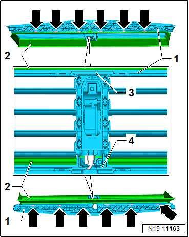
Arrangement of louvres 1 - Left flaps 2 - Flaps right side Flecha - Control flap
Protected by copyright. Copying for private or commercial purposes, in part or in whole, is not permitted unless authorised by SEAT S.A. SEAT S.A does not guarantee or accept any liability with respect to the correctness of information in this document. Copyright by SEAT S.A.
21 – Turbocharging/supercharging
1 Turbocharger
⇒ “1.1 Assembly overview - turbocharger”, page 351 ⇒ “1.2 Removing and installing turbocharger”, page 353 ⇒ “1.3 Removing and installing charge pressure positioner V465 ”, page 358 ⇒ “1.4 Removing and installing connection for turbocharger”, page 360
1.1 Assembly overview - turbocharger
⇒ “1.1.1 Assembly overview - turbocharger, part 1”, page 351 ⇒ “1.1.2 Assembly overview - turbocharger, part 2”, page 352
1.1.1 Assembly overview - turbocharger, part 1
1 - Turbocharger union ❑ Removing and installing ⇒ page 360 2 - Bolt ❑ 8 Nm
3 - O-ring ❑ Renew after removal ❑ Before installing, lightly moisten O-ring with clean engine oil Protected by copyright. Copying for private or commercial purposes, in part or in whole, is not permitted unless authorised by SEAT S.A. SEAT S.A does not guarantee or accept any liability with4 - Seal respect to the correctness of information in this document. Copyright by SEAT S.A.❑ Renew after removal
5 - Support ❑ for coolant lines
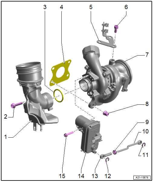
6 - Bolt ❑ 20 Nm
7 - Turbocharger ❑ Can only be renewed to‐gether with exhaust manifold ❑ Removing and installing ⇒ “1.2 Removing and in‐stalling turbocharger”, page 353 8 - Nut ❑ Renew after removal ❑ 25 Nm
9 - Lock nut ❑ For charge pressure po‐sitioner - V465❑ 10 Nm
10 - Operating lever ❑ For charge pressure positioner - V465-


