9 minute read
3.4 Removing and installing camshaft adjuster


❑ Lubricate contact surfaces before installing. 9 - Securing clip ❑ For hydraulic compensation element 10 - Hydraulic compensation element ❑ Do not interchange ❑ Oil contact surface
Installation position: valve springs • The end with smaller diameter -a- must face towards valve spring plate. • The end with larger diameter -b- must face towards cylinder head.
3.2 Measuring axial play of camshaft
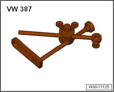
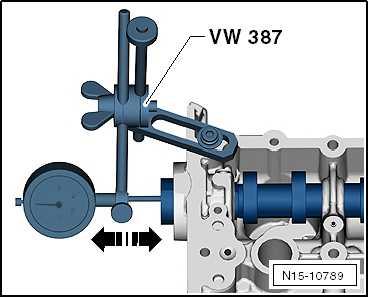
Special tools and workshop equipment required ♦ Universal dial gauge bracket - VW 387-
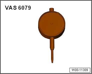
♦ Dial gauge - VAS 6079-
Protected by copyright. Copying for private or commercial purposes, in part or in whole, is not permitted unless authorised by SEAT S.A. SEAT S.A does not guarantee or accept any liability with respect to the correctness of information in this document. Copyright by SEAT S.A.

Procedure
– Remove camshaft housing ⇒ page 166 . – Secure universal dial gauge bracket - VW 387- with dial gauge - VAS 6079- to camshaft housing, as shown in illustration. – Press camshaft against dial gauge by hand. – Set dial gauge to “0”. – Prise camshaft off dial gauge and read off value. Axial clearance:
• Wear limit: 0.25 mm
3.3 Removing and installing camshaft oil seal
⇒ “3.3.1 Removing and installing camshaft oil seal, inlet cam‐shaft”, page 206 ⇒ “3.3.2 Removing and installing camshaft oil seal, exhaust cam‐shaft, pulley end”, page 208 ⇒ “3.3.3 Removing and installing camshaft oil seal, exhaust cam‐shaft, gearbox end”, page 209
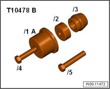
Special tools and workshop equipment required ♦ Assembly tool - T10478 B-
Protected by copyright. Copying for private or commercial purposes, in part or in whole, is not permitted unless authorised by SEAT S.A. SEAT S.A does not guarantee or accept any liability with ♦ respect to the correctness of information in this document. Copyright by SEAT S.A.Puller hooks - T20143-

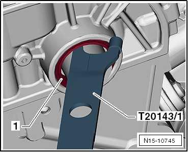
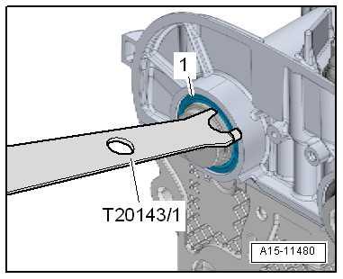
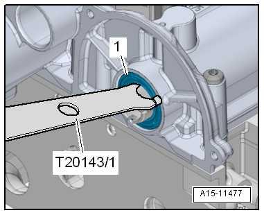
Removing – Remove toothed belt from camshafts ⇒ page 198 . – Remove camshaft adjuster for inlet camshaft ⇒ page 211 . – Pull out oil seal -1- using extractor tool -T20143/1- .
Installing
Note
Do not lubricate new oil seal.
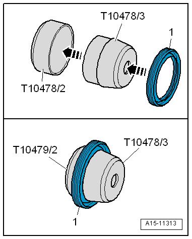
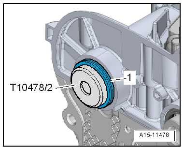
– Slide oil seal -1- over fitting sleeve -T10478/3- onto guide sleeve -T10478/2- .
• Installation position: The closed side of the oil seal faces the guide sleeve. – Separate fitting sleeve and guide sleeve.
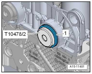
– Fit guide sleeve -T10478/2- with oil seal -1- onto camshaft.
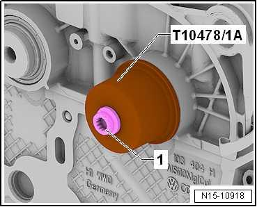
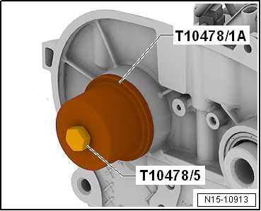
– Draw in seal to stop using thrust piece -T10478/1A- and bolt -1- for camshaft pulley. – Install toothed belt ⇒ “2.6 Adjusting valve timing”, page 189 .
Protected by copyright. Copying for private or commercial purposes, in part or in whole, is not permitted unless authorised by SEAT S.A. SEAT S.A does not guarantee or accept any liability with respect to the correctness of information in this document. Copyright by SEAT S.A.
Special tools and workshop equipment required ♦ Assembly tool - T10478 B-
♦ Puller hooks - T20143-
Removing – Remove toothed belt from camshafts ⇒ “2.7 Removing toothed belt from camshaft”, page 198 . – Separate the engine support to free some space ⇒ “1.5 Removing and installing engine support”, page 122 . – Remove camshaft adjuster for exhaust camshaft ⇒ page 215 . – Pull out oil seal -1- using extractor tool -T20143/1- .
Protected by copyright. Copying for private or commercial purposes, in part or in whole, is not permitted unless authorised by SEAT S.A. SEAT S.A does not guarantee or accept any liability with respect to the correctness of information in this document. Copyright by SEAT S.A.
Installing
Note
Do not lubricate new oil seal.
– Slide oil seal -1- over fitting sleeve -T10478/3- onto guide sleeve -T10478/2- .
• Installation position: The closed side of the oil seal faces the guide sleeve. – Separate fitting sleeve and guide sleeve.
– Fit guide sleeve -T10478/2- with oil seal -1- onto camshaft.
– Pull in thrust piece -T10478/1A- with bolt -T10478/5- as far as stop. – Install toothed belt ⇒ “2.6 Adjusting valve timing”, page 189 . – Installing engine support ⇒ page 122 .
Protected by copyright. Copying for private or commercial purposes, in part or in whole, is not permitted unless authorised by SEAT S.A. SEAT S.A does not guarantee or accept any liability with respect to the correctness of information in this document. Copyright by SEAT S.A.
Special tools and workshop equipment required
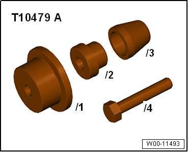
♦ Assembly tool - T10479A-
♦ Puller hooks - T20143-
Removing – Remove pump gear of the coolant pump ⇒ “2.7 Removing and installing toothed belt pulley for coolant pump”, page 294 . – Carefully slide extractor tool -T20143/1- between camshaft and oil seal -1-.
– Pry out oil seal.
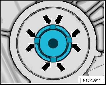
Installing – Remove any burrs in outer area of grooves in exhaust cam‐shaft -arrows- using fine sandpaper “220 ... 1000 grade”.
Note
Protected by copyright. Copying for private or commercial purposes, in part or in whole, is not permitted unless authorised by SEAT S.A. SEAT S.A does not guarantee or accept any liability with respect to the correctness of information in this document. Copyright by SEAT S.A.
Do not lubricate new oil seal.
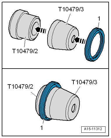
– Slide seal -1- over fitting sleeve - T10479/3- onto guide sleeve - T10479/2- .
• Installation position: The closed side of the oil seal faces the guide sleeve - T10479/2- . – Separate fitting sleeve - T10479/3- and guide sleeve T10479/2- .
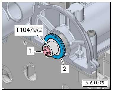
– Fit guide sleeve - T10479/2- together with oil seal centrally on camshaft.
– Secure guide sleeve onto camshaft using bolt -1- for coolant pump drive sprocket. – Slide oil seal onto camshaft and unbolt guide sleeve.
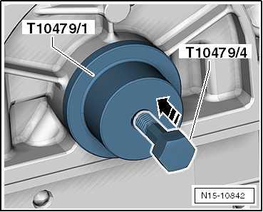
– Using press tool -T10479/1- and screw -T10479/4- press the shaft seal to the stop. – Install pump gear of the coolant pump. ⇒ “2.7 Removing and installing toothed belt pulley for coolant pump”, page 294
Protected by copyright. Copying for private or commercial purposes, in part or in whole, is not permitted unless authorised by SEAT S.A. SEAT S.A does not guarantee or accept any liability with respect to the correctness of information in this document. Copyright by SEAT S.A.
3.4 Removing and installing camshaft ad‐juster
⇒ “3.4.1 Removing and installing camshaft adjuster for inlet cam‐shaft”, page 211 ⇒ “3.4.2 Removing and installing camshaft adjuster for exhaust camshaft”, page 215
Special tools and workshop equipment required
♦ Assembly tool - T10476A-
♦ Counter-hold tool - T10554-

Protected by copyright. Copying for private or commercial purposes, in part or in whole, is not permitted unless authorised by SEAT S.A. SEAT S.A does not guarantee or accept any liability with respect to the correctness of information in this document. Copyright by SEAT S.A.

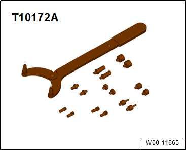
♦ Counter-hold tool - T10172A-
Removing – Set engine to “TDC for cylinder no. 1” ⇒ “4.7 Setting piston to TDC position”, page 155 . – Remove toothed belt from camshafts ⇒ page 198 . – Secure camshaft against turning with counterhold - T10554and counterhold - T10172A- .
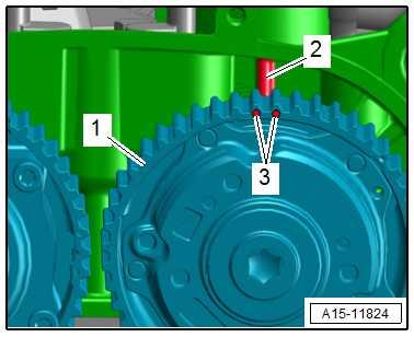
– Unscrew bolt -2- for camshaft adjuster of inlet camshaft. – Remove camshaft adjuster of inlet camshaft. – Seal camshaft adjusters immediately using suitable plug from engine bung set - VAS 6122- .
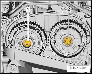
Installing – Install camshaft adjuster. – Renew bolts -3- and -4- for camshaft adjusters, and screw them in loosely. • It should just be possible to turn camshaft pulleys -1- and -2on camshafts but no rocking is permissible. • Camshafts are located in “TDC” position. • The camshaft pulleys are properly aligned with each other. • Crankshaft is in “TDC position”.
Note
♦ Renew bolts that are tightened with turning further angle. ♦ Renew O-ring of plug if damaged. ♦ Ensure that the guide sleeve ⇒ Item 11 (page 175) is reinstal‐led.
– Centre marks -3- of inlet camshaft pulley -1- relative to web -2- on camshaft housing.
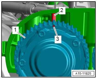
– Centre marks -3- of exhaust camshaft pulley -1- relative to web -2- on camshaft housing.
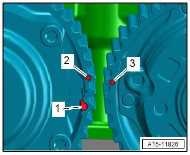
• The items -2- and -3- must be slightly offset. • Groove -1- is used to check whether the assembly tool T10476A- has been inserted correctly.
Protected by copyright. Copying for private or commercial purposes, in part or in whole, is not permitted unless authorised by SEAT S.A. SEAT S.A does not guarantee or accept any liability with respect to the correctness of information in this document. Copyright by SEAT S.A.