1 minute read
2.8 Removing and installing tensioning roller


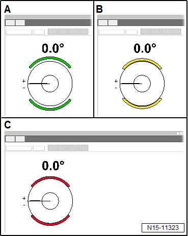
– Make sure that brake indicator on display is green -A-. – It must not be yellow or red.
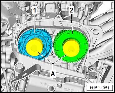
– Seal camshaft adjusters -1- and -2- using suitable plugs -Afrom engine bung set - VAS 6122- . – Fit a new piece of paper into plugs -A- to catch the engine oil. – The plug for the camshaft adjuster -1- on exhaust side must be pushed in slightly. – Turn crankshaft 2 turns in direction of rotation of engine. – Screw in locking pin - T10340- . – Set piston for cylinder no. 1 to TDC position ⇒ “4.7 Setting piston to TDC position”, page 155 . – Check valve timing ⇒ “2.5 Checking valve timing”, page 187 .
NOTICE
Adjust valve timing as precisely as possible. The settings must be as close to the specifications as possible. The valve timing must not be outside the tolerance limits.
– Read valve timing, and compare it with specifications.
Specified angle in °
Protected by copyright. Copying for private or commercial purposes, in part or in whole, is not permitted unless authorised by SEAT S.A. SEAT S.A does not guarantee or accept any liability with respect to the correctness of information in this document. Copyright by SEAT S.A.
Inlet camshaft Exhaust camshaft
+1.1° ±1.5° +0.8° ±1.5°
– If necessary, adjust timing again ⇒ “2.6 Adjusting valve timing”, page 189 . Assembly is carried out in the reverse order. Observe the follow‐ing: – Unscrew locking pin - T10340- . – Make sure that brakes a are released on both sides.

– Tighten camshaft adjuster on intake camshaft to specified final torque ⇒ “3.4.1 Removing and installing camshaft adjuster for inlet camshaft”, page 211 . – Tighten camshaft adjuster on exhaust camshaft to specified final torque


