
3 minute read
1.5 Checking compression


– Unscrew bolts -arrows- and remove heat shield -1-.
– Remove heat-shield sleeve
– Disconnect connector -arrow- for coolant temperature sender - G62- .
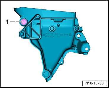
– Unscrew bolt -1- from engine support.

Protected by copyright. Copying for private or commercial purposes, in part or in whole, is not permitted unless authorised by SEAT S.A. SEAT S.A does not guarantee or accept any liability with respect to the correctness of information in this document. Copyright by SEAT S.A.

– Loosen cylinder head bolts in the sequence -1 … 8-, and un‐screw them.
– Take off cylinder head and set it down on a soft surface (foam plastic). Installing
Note
♦ Risk of damage to sealing surfaces. ♦ Carefully remove sealant residue from cylinder head and cyl‐inder block.
♦ Ensure that no long scores or scratches are made on the sur‐faces, while doing so. ♦ Risk of damage to cylinder block. ♦ No oil or coolant must be allowed to remain in the blind holes for the cylinder head bolts in the cylinder block. ♦ Risk of leaks in cylinder head gasket. ♦ Carefully remove remains of emery and abrasives. ♦ Do not remove new cylinder head gasket from packaging until it is ready to be fitted. ♦ Handle the cylinder head gasket very carefully to prevent damage to the silicone coating or the indented area of the gasket. ♦ If a further tightening angle is specified for certain bolts, these must be renewed.
♦ Renew self-locking nuts, seals, gaskets and O-rings. ♦ When installing a replacement cylinder head, the contact sur‐faces between hydraulic compensation elements, roller rocker fingers and running surface of cams must be oiled before in‐stalling the camshaft housing. ♦ Secure all hose connections with hose clips according to pro‐duction standard ⇒ Electronic Parts Catalogue . ♦ After fitting a new cylinder head or cylinder head gasket, change the coolant and engine oil.

Protected by copyright. Copying for private or commercial purposes, in part or in whole, is not permitted unless authorised by SEAT S.A. SEAT S.A does not guarantee or accept any liability with respect to the correctness of information in this document. Copyright by SEAT S.A.
– Fit cylinder head gasket -1-. ♦ Pay attention to dowel sleeves -arrows- in cylinder block. ♦ Note the installation position of cylinder head gasket. Identifi‐cation: part No. -2- should be legible from inlet side. – If crankshaft has been rotated in the meantime: set No. 1 cyl‐inder piston to top dead centre and then turn crankshaft back slightly. – Fit cylinder head. – Insert and cylinder head bolts and tighten hand-tight. – Tighten bolts for cylinder head cover ⇒ page 159 .
Note
After repair work it is not necessary to retighten the cylinder head bolts.
Carry out the remaining installation in reverse sequence, noting the following: – Install turbocharger. ⇒ “1.2 Removing and installing turbocharger”, page 353 – Install camshaft housing ⇒ “1.4 Removing and installing camshaft housing”, page 166 . – Electrical connections and routing ⇒ Electrical system; Rep. gr. 97 ; Relay carriers, fuse carriers, electronics boxes; Over‐view of fitting locations - relay carriers, fuse carriers, electron‐ics boxes and ⇒ Current flow diagrams, Electrical fault finding and Fitting locations. Change engine oil ⇒ “1.2 Engine oil:”, page 237 . – Fill cooling system with fresh coolant ⇒ “1.3 Draining and adding coolant”, page 260 . Specified torques ♦ ⇒ “2.1 Assembly overview - assembly mountings”, page 67 ♦ ⇒ “1.1 Assembly overview - cylinder head”, page 158 ♦ ⇒ “1.1 Assembly overview - turbocharger”, page 351 ♦ ⇒ “4.1 Assembly overview - intake manifold”, page 399
1.4 Removing and installing camshaft hous‐ing
Special tools and workshop equipment required

Protected by copyright. Copying for private or commercial purposes, in part or in whole, is not permitted unless authorised by SEAT S.A. SEAT S.A does not guarantee or accept any liability with respect to the correctness of information in this document. Copyright by SEAT S.A.


