
4 minute read
4.7 Setting piston to TDC position


5 - Oil scraper rings ❑ Carefully remove and install 3-part oil scraper rings by hand ❑ Checking ring gap ⇒ page 152 . ❑ Ring-to-groove clearance not measurable. 6 - Conrod bolt ❑ Renewing ❑ To measure radial clearance, tighten to corresponding specified torque but not further. ❑ Oil threads and contact surface ❑ 30 Nm +90°
7 - Conrod bearing cap ❑ Check fitting position ❑ The caps only fit in one position and only on the appropriate conrod due to the breaking procedure (cracking) separating the cap from the conrod. ❑ Mark with cylinder number prior to removal -A-. ❑ Installation position: the marking -B- points toward the belt pulley (if there is no marking, this must be made before removing). 8 - Bearing race ❑ Fitting position ⇒ page 150 ❑ Do not interchange used bearing shells. ❑ Insert bearing shells centrally. Checking radial clearance with Plastigage: ❑ New: 0.020 ... 0.060 mm ❑ Wear limit: 0.070 mm ❑ Do not rotate crankshaft when checking radial clearance. 9 - Pressure relief valve ❑ Opening pressure of pressure relief valve: 1.8 … 2.2 bar ❑ 27 Nm
10 - Oil spray jet ❑ For piston cooling. ❑ Removing and installing ⇒ page 153 11 - Connecting rod
Protected by copyright. Copying for private or commercial purposes, in part or in whole, is not❑ Renew as set only. permitted unless authorised by SEAT S.A. SEAT S.A does not guarantee or accept any liability with❑ Mark with cylinder number -A-.respect to the correctness of information in this document. Copyright by SEAT S.A. ❑ Installation position: the marking -B- points toward the belt pulley (if there is no marking, this must be made before removing). ❑ Piston axial guided ❑ Separating new conrod ⇒ “4.4 Separating new conrod”, page 152 .
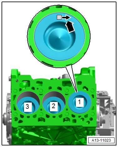
Installation position and allocation of piston to cylinder
Note
♦ Risk of damage to piston crown. ♦ If worn pistons are to be reinstalled, mark their allocation to the cylinder on the piston crown. Use paint for this. ♦ Do not use indentation, scratches, notches, or similar to mark the piston crown.
• Arrow on piston crown points to pulley end -arrow-.
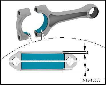
Bearing shells - installation position – Centre bearing shells on conrod and in conrod bearing cap. • Distance -a- = distance -a-.
Protected by copyright. Copying for private or commercial purposes, in part or in whole, is not permitted unless authorised by SEAT S.A. SEAT S.A does not guarantee or accept any liability with respect to the correctness of information in this document. Copyright by SEAT S.A.
4.2 Removing and installing pistons
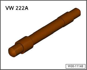
Special tools and workshop equipment required ♦ Drift - VW 222 A-
♦ Piston ring clamp, commercially available Removing – Remove cylinder head ⇒ “1.3 Removing and installing cylinder head”, page 162 . – Remove sump ⇒ “1.3 Removing and installing sump”, page 237 and baffle plate. – Mark piston installation position and corresponding cylinder number.
– Mark installation position and matching of cylinder and conrod bearing cap to conrod ⇒ Item 7 (page 149) . – Remove conrod bearing cap and withdraw piston and conrod upwards.
Note
If the piston pin is difficult to move, heat the piston to approx. 60 ° C.
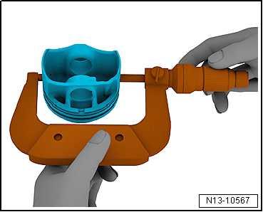
– Remove retaining ring from piston pin eye. – Drive out piston pin using drift - VW 222 A- . Installing Install in reverse order of removal, observing the following:
Note
If a further tightening angle is specified for certain bolts, these must be renewed.
– Oil running surfaces of shell bearings. – Install piston using commercially available piston ring clamp; note installation position ⇒ page 150 . – Install conrod bearing cap, noting installation position ⇒ Item 7 (page 149) . – Install cylinder head ⇒ “1.3 Removing and installing cylinder head”, page 162 . – Install oil pan ⇒ “1.3 Removing and installing sump”, page 237 . Specified torques ♦ ⇒ “4.1 Assembly overview - pistons and conrods”, page 148
4.3 Checking pistons and cylinder bores
Special tools and workshop equipment required ♦ External micrometer 50-75 mm - VAS 6070-
Checking piston – Using an external micrometre, measure approx. 10 mm from
Protected by copyright. Copying for private or commercial purposes, in part or in whole, is notlower edge, offset 90° from piston pin axis. • permitted unless authorised by SEAT S.A. SEAT S.A does not guarantee or accept any liability with respect to the correctness of information in this document. Copyright by SEAT S.A.Maximum deviation from nominal dimension: 0.04 mm.
Piston diameter, mm
Specification 74.42 1 • 1) Dimensions not including coating (thickness 0.018 mm on each side).


