1 minute read
4.2 Removing and installing pistons


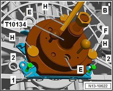
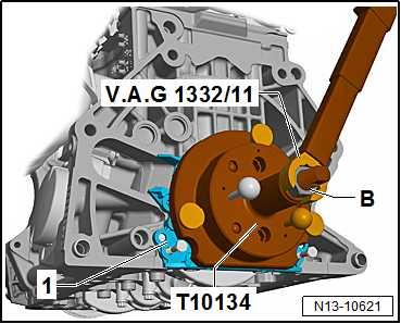
Re-pressing sender wheel: – Secure assembly tool - T10134- on crankshaft flange -1-. – Make sure that the locating pin of assembly tool - T10134- is properly seated in sender wheel hole. – Tighten hexagon socket head bolts -E- by hand. – Push assembly tool - T10134- by hand against sealing flange -1-.
– Screw nut -B- by hand onto threaded spindle until it rests against assembly tool - T10134- . – Push guide pin for petrol engines (red knob) -F- into crankshaft flange. – Screw knurled screws -H- into sealing flange -1-. – To guide sealing flange, screw 2 M6 x 35 mm bolts -2- into cylinder block.
Protected by copyright. Copying for private or commercial purposes, in part or in whole, is not permitted unless authorised by SEAT S.A. SEAT S.A does not guarantee or accept any liability with– Tighten nut -B- of assembly tool - T10134- to 40 Nm. respect to the correctness of information in this document. Copyright by SEAT S.A.– Check sender wheel installation position on the crankshaft again ⇒ page 143 . – If specification is not achieved, tighten nut of assembly tool T10134- to 45 Nm.

– Check sender wheel installation position on the crankshaft again ⇒ page 143 . Assembling: – Tighten sealing flange bolts diagonally and alternately. – Install oil pan ⇒ “1.3 Removing and installing sump”, page 237 . – Install intermediate plate ⇒ page 136 . – Install flywheel ⇒ “2.2 Removing and installing flywheel”, page 136 . – Install gearbox ⇒ Rep. gr. 34 ; Removing and installing gear‐box .
– Check valve timing ⇒ “2.5 Checking valve timing”, page 187 . Specified torques ♦ ⇒ Fig. ““Sealing flange on gearbox side - specified torque and tightening sequence”“ , page 136 ♦ ⇒ “2.1 Assembly overview - cylinder block, gearbox end”, page 135
♦ Engine speed sender - G28⇒ “1.1 Assembly overview - ignition system”, page 464


